background image

Page


|


22


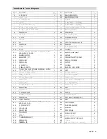
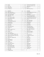
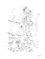
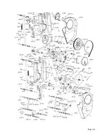
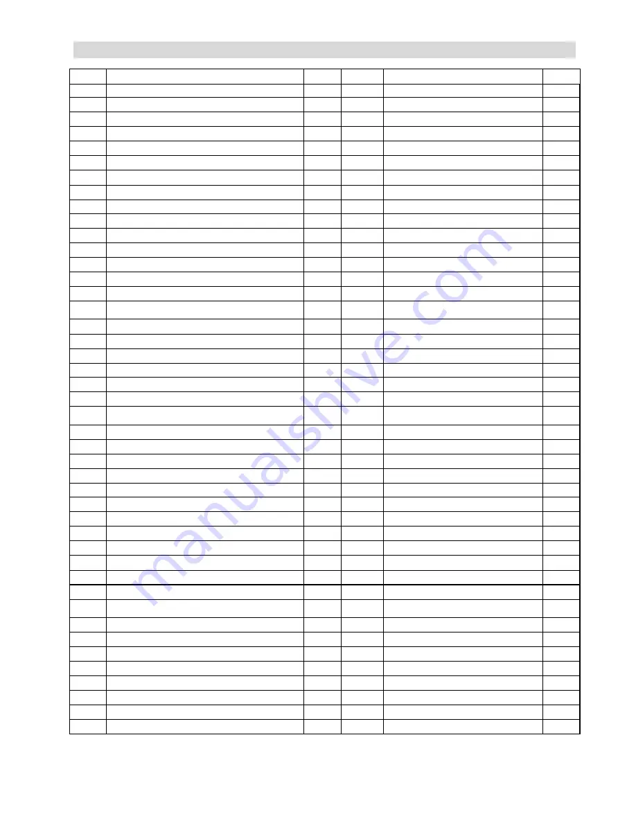
Parts List & Parts Diagram 

P/N 

DESCRIPTION Qty 

P/N 

DESCRIPTION 

Qty 

A MAIN 

FRAME 

A51 BELT WHEEL 

360(J10) 

A1 SENSOR 

WIRE 

A52 BELT 

530(1355MM)*J8 

A2 CONTROLLER 

WIRE 

A53 NUT 

M8 

10 

A3 KNOB 

A54 

OSCILLATING AXLE BASE (R)

 1 

A4 

CONNECTION SLICE 40 (4T) 

A55 

OSCILLATING AXLE BASE (L)

 1 

A5 

INCLINE MOTOR SENSOR WIRE 

A56 

HANDLEBAR SUPPORTING COVER 

A8 

INCLINE MOTOR CONTROLLER BOX 

A57 

BEARING 6905(TPX) 

A9 SCREW 

M5*10 

A58 END CAP 

4” 

A10 ADAPTOR 

A59  FIX CUSHION 

50 TPR 

A11 DC 

WIRE 

A60  WASHER M6*2T*

19 

A12 SOCKET 

A61  SCREW 

3/16”*5/8” 

A13 

NUT 

A62 

FRONT CONNECTING SHAFT 

A14 SCREW 

M3*8 

A63  END 

CAP 

A15 SENSOR 

A64  BUSH 

8*(

12+

15) 

A16 MOTOR 

A65  CLIP(R36) 

12 

A17 

CONNECTION CABLE BETWEEN OVERLOAD SWITCH 

AND SWITCH AC POWER 

1 A67 

BEARING SLEEVE

42*3T 

12 

A18 

BEARING 6005(TPX) 

A69 

NUT M4 

10 

A19 

BRAKE DEVICE (3T) 

A71 

CRANK CONNECTING SHAFT 

A20 SCREW 

M6*43 

A72  BEARING 

2203(MRB) 

A21 SCREW 

M8*16 

A73  NUT 

M10 

A22 WASHER(10*12) 

A74 

CLIP(R40) 2 

A23 OVERLOAD 

SWITCH 

A75 

BUSH L724 

8(

11.9+

15) 

A24 

CONNECTION WIRE BETWEEN OVERLOAD SWTICH 

AND SWITCH AC POWER 

1 A76 

NUT 

A25 

POWER CONNECTION WIRE 

A77 

FLAT KEY 7*7*20MM 

A26 SWITCH 

AC 

POWER 

A78  WASHER M17*

35*2T 

12 

A27 

POWER CORD SOCKET 

A79 

SCREW M8*50 

A28 

SCREW M3*10 

A80 

FRONT PEDAL SUPPORTING TUBE 

A29 SCREW 

M8*10 

A81  WASHER 

10*

27*2T 

A30 TRANSPORTATION 

WHEEL 

A82  SCREW 

M10*40MM 

A31 SCREW 

M8*45 

A83  NUT 

A32 PRESSING 

PIPE 

A84  SCREW 

A33 

WASHER 

10*

23*2T 

3 A85 

SPRING 

A34 

BEARING 6200(MRB) 

A86 

MOTOR PUSH ROD 

A35 

SCREW M10*30 

A87 

AXLE FOR MOTOR PUSH ROD 

A36 

J SHAPE SCREW M6 

A88 

NUT 

A37 

CONNECTION WIRE BETWEEN SWITCH AC POWER 

AND POWER CORD 

1 A89 

NYLON 

SLEEVE 

A38 

WASHER M6*

16*2T 

A90 

PUSH ROD BRACKET 

A39 GROUND 

WIRE 

A91 END 

CAP 

A40 POWER 

CORD 

A92 

SPACER SHIM 

A41 

FLYWHEEL 

327 

1 A93 

SCREW 

M8*25MM 

A42 NUT 

3/8” 

A94  SCREW M6*40 

A43 

TENSION CABLE 400MM 

A95 

SCREW 5/32”*3/4”(M4*19MM) 

11 

A44 SCREW 

M5*10 

A96  NUT M6 

A45 

TURING PLATE 

2 A97 

SIDE DECORATION HOUSING SET(L) 

Summary of Contents for VST-V8

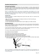
Page 1: ...User s Product Manual LifeCORE VST V8 Variable Stride Trainer...

Page 2: ...he best it can be please review the enclosed user s manual prior to assembly and first use Be sure to keep the instructions for reference and or maintenance We also offer a complete line of fitness eq...

Page 3: ...ctions and Warnings Assembly Instructions Parts List Pedal Locking Feature How to Transport the Variable Stride Trainer Console Operation Instructions Monitoring Your Heart Rate Heart Rate Monitoring...

Page 4: ...tart your exercise program gradually Exercise only for a few minutes the first day to let your body adjust to the new exercise 2 Slowly increase your exercise time and intensity over the first two wee...

Page 5: ...e packing materials to ensure no missing parts were left behind Note that some hardware may be preassembled to components in order to help with assembly tools have also been provided to assist with as...

Page 6: ...Page 5...

Page 7: ...o help align holes C Repeat the same two steps for left side assembly Step 2 R Side Supporting Tube and Main Frame Assembly Tools Needed 5mm Allen wrench 6mm Allen wrench A As shown in Views A B Assem...

Page 8: ...pporting Tube Assembly Tools Needed 13mm wrench 6mm Allen wrench Note Use page 5 as a reference to help distinguish correct bolts for assembly Additional assistance may be needed A As shown in View D...

Page 9: ...C Repeat the same steps for the right handlebar E2 Step 6 Central Supporting Tube and Water Bottle Holder Assembly Tools Needed 5mm Allen wrench 6mm Allen wrench Note Make sure that all wires are con...

Page 10: ...le G onto the central supporting tube D D Adjust the levelers on the bottom rear of supporting tubes to stabilize the machine E Turn pedal locking feature knob to the unlock position Step 8 Power Cord...

Page 11: ...ng feature while the machine is in motion only when it is at a full complete stop is it safe to move the knob How to Transport the Variable Stride Trainer If the machine needs to be transported to a d...

Page 12: ...choose from Below is the console layout and detailed operation instructions Make sure the VST is powered up before you start using this console This product is powered by AC power please make sure the...

Page 13: ...ser load watt distance calories and pulse While setting up a program the appropriated data window will blink to indicate which data you are currently setting Rotate the adjustment dial to adjust the v...

Page 14: ...he stride length for a few reasons First reason is for height a user at or below 5 5 may feel more comfortable with 18 to 22 stride and a user at or above 5 5 may feel more comfortable with 22 to 26 s...

Page 15: ...rofile number such as U1 Press the ENTER key to confirm selected user Step 2 Setup User Gender Male or female symbol will light up Rotate the adjustment dial to change selection and press the ENTER ke...

Page 16: ...ad resistance level Dot matrix profile will light up one row and Load display will flash a 1 rotate the adjustment dial to adjust the level from 1 to 16 and press ENTER to confirm You can also adjust...

Page 17: ...ser Program This program custom program is designed for users to build a program profile segment by segment 1 20 resistance change before exercising When the adjustment dial is rotated during category...

Page 18: ...The dot matrix profile will show the selected H R C program 55 75 90 or Target Press ENTER to confirm the program Example 220 Age 45 175 X multiplied by 55 or 75 or 90 Percentage 55 96 bpm Check page...

Page 19: ...and can only be adjusted in decimals of 5 After watt entry time window will flash with 0 00 or last entered time rotate the adjustment dial to adjust the time and press ENTER to confirm After time en...

Page 20: ...r minute We recommend taking your heart rate at these times at rest after warming up during your workout and two minutes into your cool down to accurately track your progress as it relates to better f...

Page 21: ...dampening your palms may help the sensors register a more stable heart rate Chest Strap Optional The VST V8 is equipped with a built in wireless 122k receiver for your heart rate monitoring transmitt...

Page 22: ...lways clean the machine after use 1 Proper cleaning is important for longevity of a machine clean the unit with a light soap water mixture followed by a dry towel You can also use a light house hold c...

Page 23: ...RB 2 A21 SCREW M8 16 1 A73 NUT M10 2 A22 WASHER 10 12 2 A74 CLIP R40 2 A23 OVERLOAD SWITCH 1 A75 BUSH L724 8 11 9 15 8 A24 CONNECTION WIRE BETWEEN OVERLOAD SWTICH AND SWITCH AC POWER 1 A76 NUT 2 A25 P...

Page 24: ...1 E2 HANDLE BAR R 1 B10 PEDAL REST R 1 E3 END CAP 1 1 4 2 B11 FRONT COVER PEDAL L 1 E4 SPONG HDR 30 3T 390 2 B12 CUSHION PAD L 1 E5 CONNECTION SLICE 38 4T 4 B13 PEDAL L 1 F1 SIDE CONNECTING BOTTOM L...

Page 25: ...Page 24...

Page 26: ...Page 25...

Page 27: ...ct serial number has been defaced or removed Should any Product be submitted for warranty service be found ineligible an estimate of repair cost will be furnished Warranty Service Area Any labor cost...

Page 28: ...LifeCORE reserves the right to change manufacturers of any parts to cover any existing warranty Any parts determined to be defective must be returned to LifeCORE to obtain warranty service You must p...

Page 29: ...omer Service Toll Free 888 815 5559 Mon Friday 7 30 5 30 PT Service LifeCOREfitness com LifeCORE Fitness Inc 2575 Pioneer Ave Suite 101 Vista CA 92081 Visit our website for assembly videos www LifeCOR...

Reviews: