12
Hardware:
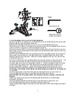
4. Seat Sliding Tube, Back/Seat Support Bracket, and Handlebar
Installation
Remove eight Ø8 Washers (36) and M8x15 Bolts (72) from the Seat Sliding Tube (52).
Insert the Seat Sliding Tube (52) into the Bushings (61) of the Rear Main Frame (46).
Attach the Seat Sliding Tube (52) to the Back and Seat Support Bracket (53) with eight Ø8
Washers (36) and M8x15 Bolts (72) that were removed. Tighten bolts with the Allen
Wrench provided.
Adjust the seat position and insert the Round Knob (60) and Triangle Knob (23). Turn the
Round Knob (60) and Triangle Knob (23) in the clockwise direction to tighten.
Attach the Handlebar (68) onto the Back and Seat Support Bracket (53) with two M8x45
Bolts (57), Ø8 Curve Washers (4), Ø8 Washers (36), and M8 Cap Nuts (3). Tighten bolts
with the Multi Hex Tool with Phillips Screwdriver provided.
Connect the Middle Section Hand Pulse Sensor Wires (44) from the Rear Main Frame (46)
to the Hand Pulse Sensor Wire (56) from the Handlebar (68).
Adjusting the Seat
Release the Triangle Knob (23) from the Rear Main Frame (46). Turn the Round Knob (60)
in a counterclockwise direction until it can be pulled out. Pull out the Round Knob (60) and
then slide the Back and Seat Support Bracket (53) back or forth direction to the suitable
position. Lock the Back and Seat Support Bracket (53) in place by releasing the Round
Knob (60) and sliding the Back and Seat Support Bracket (53) back or forth slightly until the
Round Knob (60) "pops" down into the hole of the Seat Sliding Tube (52). For added safety,
tighten the Round Knob (60) and Triangle Knob (23) in a clockwise direction.
NOTE: When adjusting the seat back or forth direction, the maximum insert depth
mark line cannot over than the edge of Bushing (61).
2 Washers (Ø8)
2 Curve Washers (Ø8)
2 Bolts (M8x45)
Allen Wrench S6
Tool:
Multi Hex Tool with
Phillips Screwdriver
57
3
3
52
72
3
72
3
3
72
72
8
4
53
5
23
0
4
61
4444
6
6
6
6
6
6
6
6
2 Cap Nuts (M8)


