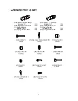
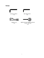
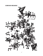
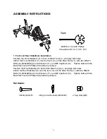
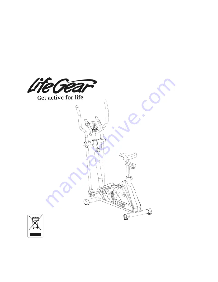
background image

ADVANCED,  

2 in 1 ELLIPTICAL TRAINER 

ITEM NO.: 93396 


OWNER’S MANUAL


IMPORTANT: Read all instructions carefully before using this product.    Retain this 
owner’s manual for future reference. 

The specifications of this product may vary from this photo, subject to change without notice. 

2010, Aug.


Summary of Contents for 93396

Page 1: ...O 93396 OWNER S MANUAL IMPORTANT Read all instructions carefully before using this product Retain this owner s manual for future reference The specifications of this product may vary from this photo s...

Page 2: ...n installed and operated in accordance with LifeGear s Owner s Manual LifeGear s obligation under this warranty is limited to replacing or repairing free of charge any parts which may prove to be defe...

Page 3: ...edal at your side at the lowest position step on the pedal and stride over the main frame then step on the other pedal When using please hold the handlebar by hands make the pedals running smoothly by...

Page 4: ...nd knob in a clockwise direction NOTE When adjusting the height of seat post the maximum insert depth mark line cannot higher than the edge of plastic bushing Adjusting the Seat Forward or Back Turn t...

Page 5: ...me and then start to exercise time starts counting down from preset target time to 0 00 per 1 second backward When the preset target time counts down to 0 00 time will start to count up immediately an...

Page 6: ...omputer will display your current heart rate figures after you hold both two hands on handlebar grip sensors during exercise To ensure the pulse readout is more precise please always hold on to the ha...

Page 7: ...035 Front Left Stabilizer End Cap 60 1 010R Rear Right Stabilizer End Cap 60 1 036 Front Right Stabilizer End Cap 60 1 011 Big Curve Washer 20x 8 10 037 Cover Cap 40x 25x10 2 012 Cap Nut M8 4 038 Bol...

Page 8: ...e Washer for Tension Control Knob 20x 5 2 1 089 Bolt M8x10 1 062 Bolt for Tension Control Knob M5x55 1 090 Front Decorate Cover 60 1 063 Adjustable Leveler M10 2 091 Left Decorate Cover 60 1 064 Senso...

Page 9: ...3 1 PC 17 Spring Washer 20 1 PC 13L Bolt for left U Shape Bracket 1 2 1 PC 14L Left Nylon Nut 1 2 1 PC 15 Wave Washer 28x 17x0 3 1 PC 17 Spring Washer 20 1 PC 24 Nylon Nut M6 10 PCS 25 Washer 6 6 PCS...

Page 10: ...9 TOOLS Allen Wrench 8mm 1 PC Allen Wrench 6mm 1 PC Multi Hex Tool 1 PC Multi Hex Tool with Phillips Screwdriver S8 S13 S14 S15 1 PC...

Page 11: ...26 34 68 13R 16 15 20 22 21 17 14R 24 25 28 23 44 24 45 39 39 30R 78 77 77 79 75 84 83 82 59 55 6 52 57 93 24 25 24 45 66 80 72 74 70 19 69 70 69 71 47 76 81 81 31 32 18 73 89 86 86 96 67 37 37 63 87...

Page 12: ...with the Multi Hex Tool with Phillips Screwdriver provided Position the Rear Stabilizer 8 behind the Main Frame 1 and align bolt holes Attach the Rear Stabilizer 8 onto the rear curve of the Main Fra...

Page 13: ...emove the 20x 5 2 Curve Washer for Tension Control Knob 61 and M5x55 Bolt for Tension Control Knob 62 from the Tension Control Knob 51 Put the cable end of resistance cable of Tension Control Knob 51...

Page 14: ...33 onto the Left Foot Bar 2L with three M6 Nylon Nuts 24 6 Washers 25 and M6x40 Bolts 26 Remove two ST4 2x25 Phillips Self Tapping Screws 60 from the Left Foot Bar 2L Attach the Foot Bar Covers A B 30...

Page 15: ...ht of seat post the maximum insert depth mark line cannot higher than the edge of plastic bushing Remove three M8 Nylon Nuts 21 and 16x 8x1 5 Washers 22 and from underside of the Seat Cushion 104 Guid...

Page 16: ...drails 4L 4R onto the Left Right Handrail Arms 3L 3R with four M6x35 Bolts 44 6 Curve Washers 45 and M6 Nylon Nuts 24 Hardware Multi Hex Tool with Phillips Screwdriver S8 S13 S14 S15 Tool 24 45 44 44...

Page 17: ...l Arm Cover A 49L and Left Handrail Arm Cover B 50L onto the Left Handrail Arm 3L with four ST4 2x12 Screws 94 Attach the Right Handrail Arm Cover A 49R and Right Handrail Arm Cover B 50R onto the Rig...

Page 18: ...ull them out from the top end of the Front Post 5 Attach the Handlebar 6 onto the Front Post 5 with two M8x15 Bolts 38 and 16x 8 Curve Washers 93 that were removed Connect the Sensor Wire I 64 and Han...

Page 19: ...he computer console SOLUTION Remove the computer console and verify the wires that come from the computer console are properly connected to the wires that come from the front post SOLUTION Check the b...

Page 20: ...of your entire exercise routine The WARM UP is an important part of any workout It should begin every session to prepare your body for more strenuous exercise by heating up and stretching your muscles...

Page 21: ...DRICEPS STRETCH With one hand against a wall for balance reach behind you and pull your right foot up Bring your heel as close to your buttocks as possible Hold for 15 counts and repeat with left foot...

Page 22: ...an against a wall with your left leg in front of the right and your arms forward Keep your right leg straight and the left foot on the floor then bend the left leg and lean forward by moving your hips...

Reviews: