background image


9

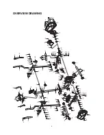
ASSEMBLY INSTRUCTIONS


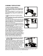
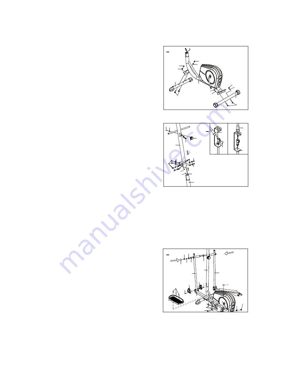
1. Install the Front/Rear Stabilizers. 

Attach the Front Stabilizer (10) onto the front curve 
plate of the Main Frame (1) with two M10x57 Bolts 
(12), Ø10 Big Curve Washers (14), and M10 Cap 
Nuts (15).   
Attach the Rear Stabilizer (11) onto the rear curve 
plate of the Main Frame (1) with two M10x57 Bolts 
(12), Ø10 Big Curve Washers (14), and M10 Cap 
Nuts (15). 


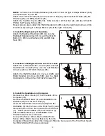
2. Install the Front Post and


Tension Control     

Knob. 

Remove six M8x16 Bolts (41), Ø8 Spring Washers 
(60), and Ø20xØ8 Curve Washers (42) from the tube 
of the Main Frame (1). 
Insert the Tension Cable (30) through into the bottom 
hole of Front Post (5) and pull it out from the square 
hole of Front Post (5).    Connect the Sensor Wire II 
(68) from the Main Frame (1) to the Sensor Wire I   
(67) from the Front Post (5).     
Insert the Front Post (5) onto the tube of the Main 
Frame (1) and secure with six M8x16 Bolts (41), Ø8 
Spring Washers (60), and Ø20xØ8 Curve Washers 
(42) that were removed.     
Remove the Ø20xØ5.2 Curve Washer for Tension 
Control Knob (64) and M5x25 Bolt for Tension 
Control Knob (65) from the Tension Control Knob 
(54).    Put the cable end of resistance cable of 
Tension Control Knob (54) into the spring hook of 
Tension Cable (30) as shown in drawing A of figure 2.   
Pull the resistance cable of Tension Control Knob 
(54) up and force it into the gap of metal bracket of 
Tension Cable (30) as shown in drawing B of figure 2.   
Attach the Tension Control Knob (54) onto the Front   
Post (5) with the Ø20xØ5.2 Curve Washer for 
Tension Control Knob (64) and M5x25 Bolt for 
Tension Control Knob (65) that were removed.


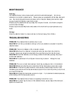
3. Install the Right/Left Handrail Arms, Right/Left       

Foot Bars, Right/Left Foot Pedals, and


Foot                                                                       

Bar Covers-A/B. 

Remove two M10x18 Bolts (43), Ø18xØ10x2 Spring 
Washers (44), Ø10 Big Washers (93), and Ø28x5 
Washers (45) from the left and right horizontal axes 
of the Front Post (5).    Then attach the Left Handrail 
Arm (3L) onto the left horizontal axis of the Front 
Post (5) with one M10x18 Bolt (43), Ø18xØ10x2 
Spring Washer (44), Ø10 Big Washer (93), and 
Ø28x5 Washer (45) that were removed.  Install a 
S16 Cap (49) onto the M10x18 Bolt (43). 
Attach the left U-Shape Bracket (23) to the left Crank (78) with one 1/2” Bolt for left U-Shape 
Bracket (16L), Ø28xØ17x0.3 Wave Washer (18), Ø20 Spring Washer (20), and 1/2” Left 
Nylon Nut (17L). Install a S13 Cap (31) onto the M8x50 Bolt (26). 

10

12

14

15

1

15

14

15

14

15

14

12

11

1

5

54

54

30

30

30

60

60

64

65

68

67

41

42 41

54

30

B

A

66

2L

28

27

29

31

66

33L

33R

3R

51

45

3L

43

44

49

5

16L(R)

18

17L(R)

36

20

26

(37)

78

93

3

1

Summary of Contents for 93560

Page 1: ...Streamline Plus Elliptical Transorbit Owner s Manual Item No 93560 The specifications of this product may vary from this photo and are subject to change without notice 2013 Dec...

Page 2: ...een installed and operated in accordance with LifeGear s Owner s Manual LifeGear s obligation under this warranty is limited to replacing or repairing free of charge any parts which may prove to be de...

Page 3: ...edal at your side at the lowest position step on the pedal and stride over the main frame then step on the other pedal When using please hold the handlebar by hands make the pedals running smoothly by...

Page 4: ...and wait 15 seconds before reinstalling 6 Removing batteries will erase the memory of computer FUNCTIONS AND OPERATIONS AUTO ON OFF When you start to exercise or press MODE button on the computer the...

Page 5: ...ur heart rate figures DIST DISTANCE Press MODE button until the arrow points to DIST the computer will display the accumulative distance traveled during workout ODO ODOMETER Press MODE button until th...

Page 6: ...ont Stabilizer 50x1 5 1 035 Bolt 15 8x62 5 2 011 Rear Stabilizer 50x1 5 1 036 Left Foot Pedal 395x150x65 1 012 Bolt M10x57 4 037 Right Foot Pedal 395x150x65 1 013 Rear Stabilizer End Cap 50x1 5 2 038...

Page 7: ...58 Hand Pulse Sensor 2 081 Flywheel 230x40x32 1 059 Handrail Foam Grip 31x 37x480 2 082 Belt PJ330 J6 1 060 Spring Washer 8 6 083 Idle Wheel Bracket 1 061 Handrail End Cap 32x1 5 2 084 Bolt M8x20 2 06...

Page 8: ...4 2x25 4 PCS 55 Screw ST2 9x12 8 PCS 50 Cap Nut M6 4 PCS 49 Cap S16 2 PCS Allen Wrench 8mm 1 PC Allen Wrench 6mm 1 PC Multi Hex Tool 1 PC Multi Hex Too Phillips Screwdriver S8 S13 S14 S15 1 PC 16R Bol...

Page 9: ...39 40 12 27 40 39 10 66 33L 33R 35 19 34 2L 12 14 15 14 15 19 37 19 23 47 50 48 19 19 33L 33R 88 86 87 85 8 73 72 74 7 25 84 84 34 35 21 55 70 66 66 77 75 72 73 22 16L 25 24 17L 20 19 23 19 18 26 31 1...

Page 10: ...the spring hook of Tension Cable 30 as shown in drawing A of figure 2 Pull the resistance cable of Tension Control Knob 54 up and force it into the gap of metal bracket of Tension Cable 30 as shown in...

Page 11: ...ft Handrail Arm Cover B 53L onto the Left Handrail Arm 3L with four ST2 9x12 Screws 55 Attach the Right Handrail Arm Cover A 52R and Right Handrail Arm Cover B 53R onto the Right Handrail Arm 3R with...

Page 12: ...mputer console SOLUTION Remove the computer console and verify the wires that come from the computer console are properly connected to the wires that come from the front post SOLUTION Check the batter...

Page 13: ...of your entire exercise routine The WARM UP is an important part of any workout It should begin every session to prepare your body for more strenuous exercise by heating up and stretching your muscles...

Page 14: ...DRICEPS STRETCH With one hand against a wall for balance reach behind you and pull your right foot up Bring your heel as close to your buttocks as possible Hold for 15 counts and repeat with left foot...

Page 15: ...an against a wall with your left leg in front of the right and your arms forward Keep your right leg straight and the left foot on the floor then bend the left leg and lean forward by moving your hips...

Reviews: