10
ASSEMBLY INSTRUCTIONS
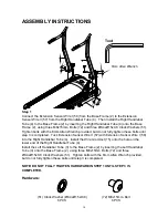
Step 1
Connect the Extension Sensor Wire I (58) from the Base Frame (2) to the Extension
Sensor Wire II (57) from the Right Handlebar Tube (4). Then Install the Right Handlebar
Tube (4) to the Base Frame (2) by inserting the Right Handlebar Tube (4) onto the Base
Frame (2), using three M8x15mm. Bolts (72) and three Ø8.4xØ15x0.8 Clock Washers (51).
Tighten bolts with the 6mm Allen Wrench provided, but do not fully tighten these bolts until
step 3 is completed. Tuck Extension Sensor Wire II (57) with Extension Sensor Wire I (58)
into the Right Handlebar Tube (4). Install the Wire Grommet (15) onto the hole on the
lower end of the Right Handlebar Tube (4).
Install the Left Handlebar Tube (3) to the Base Frame (2) by inserting the Left Handlebar
Tube (3) onto the Base Frame (2), using three M8x15mm. Bolts (72) and three
Ø8.4xØ15x0.8 Clock Washers (51). Tighten bolts with the 6mm Allen Wrench provided,
but do not fully tighten these bolts until step 3 is completed.
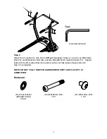
NOTE:
DO NOT FULLY TIGHTEN HARDWARE IN STEP 1 UNTIL STEP 3 IS
COMPLETED.
Hardware:
Tool:
6mm Allen Wrench
(72) M8x15mm. Bolt
6 PCS
(51) Clock Washer (Ø8.4xØ15xt0.8)
6 PCS
Summary of Contents for 97415
Page 7: ...6 OVERVIEW DRAWING ...


