background image

7

52

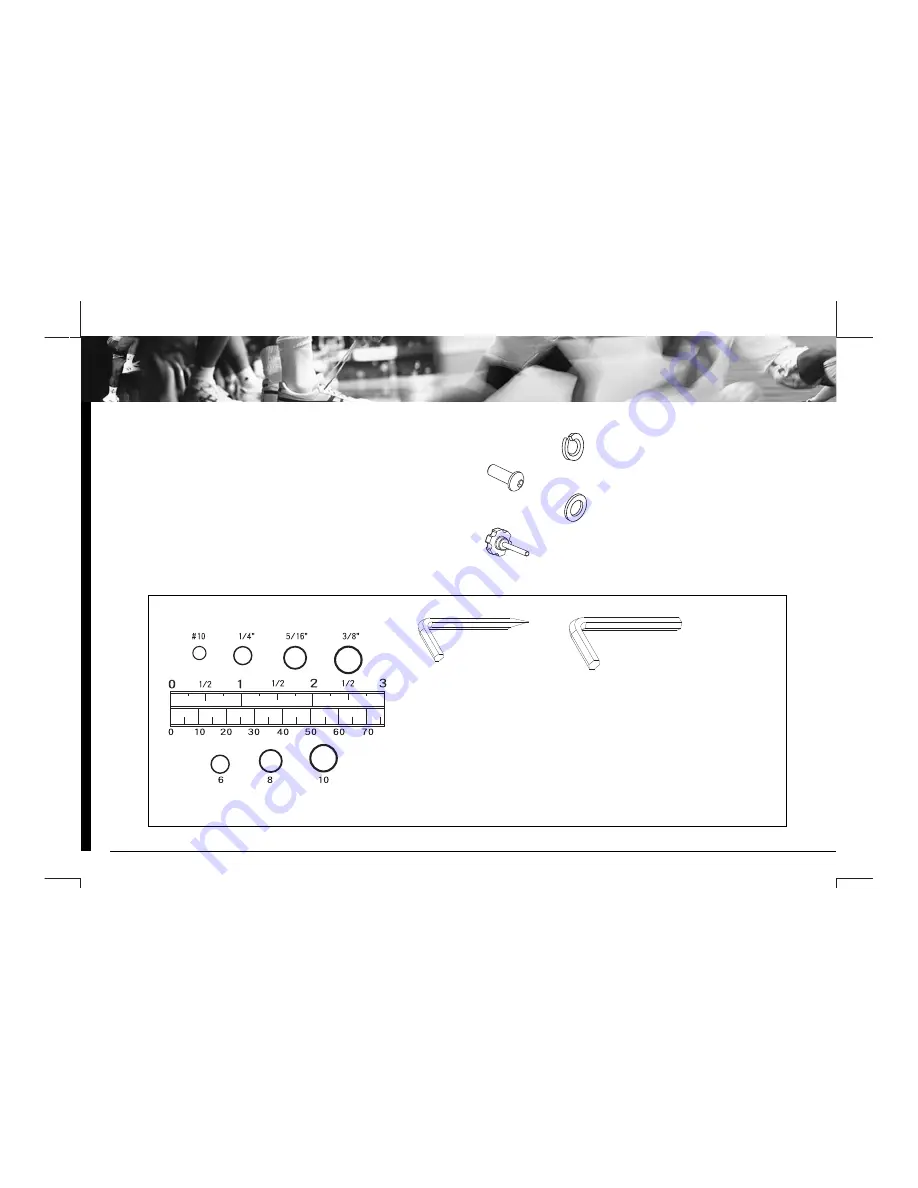
Spring Washer (M8)----------------------------------------------------------------------------------------12

70

Bolt (M8*16mm) ------------------------------------------------------------------------------------12

72

Washer (Ø 8.5*Ø 18*1.5)-----------------------------------------------------------------------------6

74

Computer Knob (M5) --------------------------------------------------------------------------------4

PLACE WASHER, BOLT’S END, OR
SCREW ON CIRCLE TO CHECK FOR 
CORRECT SIZE.

INCHES

MILLIMETERS

Part #            Description         

Quantity         

HAR

D

W

ARE P

ACKING

LIST

Summary of Contents for 97910

Page 1: ...MOTION CAPTURE MOTORIZED TREADMILL OWNER S MANUAL MODEL 97910 Get active for life 2006 Feb ...

Page 2: ...home use This warranty does not include any damage caused by improper operation misuse or commercial application From the date of purchase the frame is warranted to be free from defects for 1 one year This warranty is extended only to the original owner and is not transferable When ordering replacement parts please have the following information ready 1 Owner s Manual 2 Model Number 3 Description ...

Page 3: ...oblems arise discontinue use and consult the Authorized Service Representative zDo not use outdoors zDo not operate where aerosol spray can products are being used or where oxygen is being administered zDo not pull the treadmill by its power cord or use the cord as a handle zClose supervision is necessary if this treadmill is used by or near children persons with disabilities or pets zKeep Dry do ...

Page 4: ...d into a normal 220 volt 50 60 hz which has a grounding zKeep hands clear of all moving parts Never place hands feet under the treadmill zDo not use the treadmill on a carpet that is greater than 1 2 inch in height zBefore each use check that the running belt is aligned and centered on the treadmill bed and all visible fasteners on the treadmill are sufficiently tightened and secure WARNING BEFORE...

Page 5: ...3 33 34L 34L 34R 35 36 37R 37L 38 39 40 40 39 42 43 44 45 46 47 48 49 50 51 51 53 52 55 54 56 57 68 59 60 60 61 61 62 63 63 55 54 64 55 55 55 29 65 55 55 55 31 52 66 61 64 64 32 68 69 3 4 67 70 52 70 52 67 71 71 70 52 72 75 76 69 22 22 23 23 24 4 21 40 74 58 70 52 72 42 25 41 57 55 73 70 52 72 72 52 70 64 55 68 73 ...

Page 6: ...nsor 7R26 17F 1 27 Bracket for Sensor 1 28 Incline Beam 1 29 Cover for Incline Beam 2 30 Spacer Ø18 Ø10 5 15 5mm 2 31 Deck Bumper 8 32 End Cap 25 50 2 33 Side Rail 947mm 2 34R Rear Cap Right 1 34L Rear Cap Left 1 35 Dust Cover Upper 1 36 Dust Cover Lower 1 37R Handlebar Support Right 1 37L Handlebar Support Left 1 38 Handlebar 1 39 Foam Grip Ø30 Ø37 410 2 40 Speed Button W Wire 2 41 Connecting Wir...

Page 7: ...t M8 12 2 67 Bolt M10 100mm 2 68 Screw M4 12 11 69 Nylon Nut M4 7 70 Bolt M8 16mm 12 71 Washer Ø11 Ø21 1 8 2 72 Washer Ø8 5 Ø18 1 5 6 73 Washer Ø4 2 Ø12 0 8 4 74 Computer Knob M5 4 75 Choke 34MH 40MH 1 76 Wave Filter 06SS4 2DC1 1 77 Wire for Fuse Box CM 125 2 78 Cable Switch PCB CM 90 2 79 Wire Cap 10A 1 80 Earth Lead CM 115 1 81 Ring for Cable Power Ø26 13 1 Part Description Quantity Part Descrip...

Page 8: ...Washer M8 12 70 Bolt M8 16mm 12 72 Washer Ø8 5 Ø18 1 5 6 74 Computer Knob M5 4 PLACE WASHER BOLT S END OR SCREW ON CIRCLE TO CHECK FOR CORRECT SIZE INCHES MILLIMETERS Part Description Quantity HARDWARE PACKING LIST ...

Page 9: ...the Right Handlebar Support 37R Attach the Handlebar 38 to the Right and Left Handlebar Supports 37R 37L with six Washers 72 Spring Washers 52 and Bolts 70 Step 3 Connect the Sensor Cable I 22 and Speed Wires 40 to the wires that come from the Computer 43 Then attach the Computer 43 onto the Handlebar 38 with four Computer Knobs 74 Finally install the Safety Tether Key 44 onto the Computer 43 ASSE...

Page 10: ...a nominal 220 volt 50 60hz which has a grounding plug Step 1 Power Up zPress the Master Power Switch located at the front of the treadmill to ON position The LCD console will immediately run a self diagnostic display After that it will display current system status Step 2 Begin Workout zPress the START STOP button and then press the FAST button to begin operation zAs the running belt speed reaches...

Page 11: ...down into the locked position before moving the treadmill See diagram C TO PREVENT INJURY PLEASE MAKE SURE YOU HAVE A FIRM HOLD WHEN LIFTING UP OR SETTING DOWN THE DECK Incline Adjustment Place one hand on the rear end of Main Frame Lift the Main Frame up and then adjust the Incline Beam to the desired position Please refer to the diagrams A B and C FOLD UP INCLINE ADJUSTMENT B A A B C C ...

Page 12: ...ms h Press the MODE button to select function of SCAN TIME SPEED DISTANCE or CALORIES for displaying on the screen Button Functions START STOP To start or stop training MODE To select function of SCAN TIME SPEED DISTANCE or CALORIES during exercise To select function of TIME DISTANCE or CALORIES for target presetting in standby mode Press the MODE button for 5 second will reset the function value ...

Page 13: ...ind you and the running belt will stop automatically SPEED Display the current running speed from the minimum 0 8km to the maximal 12kms You may also press FAST or SLOW button to speed up or down your running speed during exercise DISTANCE None preset distance target Press the START STOP button and then press the FAST button the running belt starts moving with the speed at 0 8km You may press the ...

Page 14: ...remind you and the running belt will stop automatically This data is a rough guide for comparison of different exercise sessions which can not be used in medical treatment Note 1 Before training starts please make sure the safety tether key is installed on the computer properly 2 After the Master Power on and install the safety tether key on the computer the screen will display segment for 2 secon...

Page 15: ...s equipment In addition do not add any other oil ingredient otherwise the treadmill will be damaged Running Belt Adjustment After a long time of running the belt will be stretched You should turn the left and right bolts in the rear roller clockwise direction at the same position until the running belt becomes tight The running belt is adjusted at the factory it may become loose during transportat...

Page 16: ...http www lifegear com tw e mail sales lifegear com tw ...

Reviews: