


A8 / A8P Installation Manual
2
3
A8 – Accessory Overview
+
–
OUT1
+
–
OUT2
+
–
OUT3
+
–
OUT4
+
–
OUT5
+
–
OUT6
+
–
OUT7
+
–
OUT8
JP1
2
B1
B2
BR
B1
B2
BR
F1
F2
F3
F4
F5
F6
F7
F8
1
JP2
2 1
JP3
2 1
JP4
2 1
JP5
2 1
JP6
2 1
JP7
2 1
JP8
2 1
A8
1
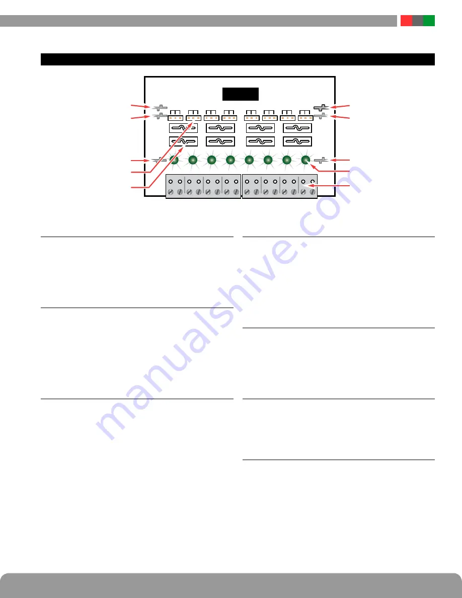
B1 Connectors (J1 & J4)
These fastons are for connection to the B1 voltage buss
in the system. The voltage on the B1 buss comes from
the first AC voltage in an FPA power supply. This volt-
age will be directed to any outputs whose Output Selec-
tion Jumper is set in the B1 position.
2
B2 Connectors (J3 & J5)
These fastons are for connection to the B2 voltage buss in
the system. The voltage on the B2 buss comes from the
second AC voltage in an FPA power supply in a dual voltage
system. This voltage will be directed to any outputs whose
Output Selection Jumper is set in the B2 position. If the A8
is being used in a single voltage system, these fastons can
be left unused.
3
BR Connectors (J2 & J6)
The AC Common buss in the system. All boards in the
system must have their BR fastons wired together for
proper operation (except for between the DC and AC
sections of an FPX hybrid system).
4
Output Selection Jumpers (JP1 – JP8)
These jumpers select which voltage buss input is select-
ed for the output. Jumper numbers correspond with the
zone number (e.g. JP1 is the jumper for OUT1). Possible
settings are as follows:
• Position 2 (Left)
– B2 Buss
• Position 1 (Right)
– B1 Buss
• Removed
– Disable Output
5
Output Fuses (F1 – F8) – Optional
When using the fused version of the A8, these are the
fuses for each zone output. Fuse numbers correspond
with the zone number (e.g. F1 is the fuse for OUT1).
When using the PTC version of the A8, the fuse will be
replaced with a soldered-in PTC.
6
Zone Outputs (Out1 – Out8)
These are the zone output terminal strips. These ter-
minal strips are removable and accept wire sizes from
AWG14 – AWG22. The terminals are labeled on the PC
board underneath the terminal strip.
7
Output LEDs (D1 – A8) – Green
These LEDs indicate the availability of voltage on a
zone’s output. When voltage is available on the output
terminals, the LED is lit. LED numbers correspond with
the zone number (e.g. D1 is the LED for OUT1).


