N24 Installation Manual
2
3
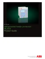
Connecting the N24 Power Distribution Module
h
Remove all AC and battery power from the FPO system before adding or replacing an N24 module.
FlexIO continues to other accessories
FlexIO in from System
Main DC voltage continues to
other accessories
Second DC Source continues to
other accessories
BR continues to other accessories
DC OUT terminals to devices to be powered
BR in from System
Input from Main
DC voltage source
Input from Second
DC source (optional)
Required Connections
Optional Connections
Each of the
B1, B2, BR,
and
FlexIO
busses
has
two connectors
.
These connectors may be used interchangeably.
For example:
FlexIO
from the power supply may be connected
to either of the N24's FlexIO connectors, the Main DC voltage
source may connect to either B1 terminal, etc.
A
B
C
D
A
B
C
D
FlexIO
B1
B2
BR
1
2
3
4
5
6
7
DataLink
N24 Board
B1
B2
BR
N24
Description
The N24 NAC Expander accessory provides up to four NAC
outputs, controlled by one or two NAC inputs. Inputs and Out-
puts can be configured as Class A or Class B. Maximum output
is 3A per output zone. The N24 is powered from a 100W or
larger FPO power supply set for 24VDC. The N24 works either
as a follower (passing along synchronization or audible cod-
ing) or generates its own synchronization or audible coding.
Regulatory Information
The equipment discussed within this manual has been tested
to the following standards:
• UL864
• ULC S527
• CSFM Approved
•
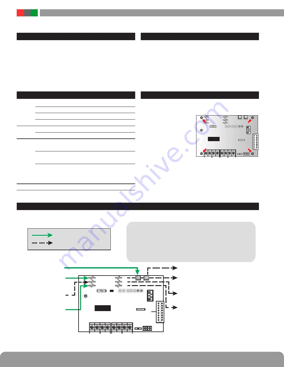
Mounting the N24 Power Distribution Module
Mounting of the board to an enclosure is via the four
snap-in standoffs supplied.
1. Locate the appropriate
mounting holes in the
enclosure and snap
the standoffs into the
holes.
2. Align the board mount-
ing holes with the
standoffs (be sure the
PC board is properly oriented) and snap the board onto
the standoffs.
N24 Board
N24
Electrical Specifications
Power
Input
Voltage
24VDC nominal ±15%
Current
12A maximum
Standby Current 100mA maximum
Alarm Current
250mA max. plus output load
Zone
Inputs
Voltage
24VDC maximum
Current
25mA maximum
Zone
Outputs
Voltage
24VDC
(Regulated 24V DC rating)
Current
3A max per output
Max. line impedance 1.5 Ohms
I
Note that the total current draw from any
buss must not exceed the capability of the
power supply powering that buss
Fuse
30A ATM automotive style


