3
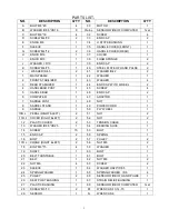
PARTS LIST
:
NO.
DESCRIPTION
Q’TY
NO.
DESCRIPTION
Q’TY
A
BOLT M8*45
4
30
MOTOR
1
B
WASHER ID8.5*OD16
8
31a,b,c
SENSOR WIRE OF COMPUTER
1set
C
BOLT M8*16
4
32
SCREW
4
D
SCREW M4*20
2
33
END CAP
2
E
KNOB M8
1
34
U STYPE BUSHING
1
F
SLEEVE
1
35
HANDLE COVER (FRONT)
1
G
SCREW M4*12
2
36
HANDLE COVER (REAR)
1
H
KNOB M16
1
37
COVER
1
I
KNOB M10
1
38
FOAM SPONGE
2
J
WASHER I.D10
1
39
END CAP
2
K
SCREW M4*25
1
40
STEEL PLATE OF HAND PULSE
2
L
WASHER ID4.5
2
41
WASHER ID4.2
2
1
MAIN FRAME
1
42
WASHER
1
2
FRONT STABILIZER
1
43
WASHER
4
3
REAR STABILIZER
1
44
END CAP WITH WHEEL
2
4
HANDLEBAR POST
1
45
SCREW
4
5
HANDLE BAR
1
46
END CAP
2
6
COMPUTER
1
47
ADAPTOR
1
7
SADDLE POST
1
48
NUT
1
8
SADDEL STAND
1
49
POWER CORD
1
9
SADDLE
1
50
FLY WHEEL
1
10R,L
PEDAL (RIGHT &LEFT)
2
51
NUT
2
11R,L
COVER (RIGHT &LEFT)
2
52
NUT
2
12
PLASTIC COVER
2
53
TENSION CABLE
1
13
WASHER ID8.5*OD25
1
54
BEARING SLICE
1
14
SCREW
15
55
BOLT
1
15
END CAP
2
56
SPRING
1
16
BOLT
2
57
PULLEY
2
17R,L
CRANK (RIGHT &LEFT)
2
58
NUT M8
2
18
BOLT M6*15
4
59
WASHER
1
19
SHAFT
1
60
BOLT
1
20
BELT TURNTABLE
1
61
BOLT
1
21
BELT
1
62
NUT M8
2
22
NUT M6
4
63
SCREW
2
23
SLEEVE
1
64
WASHER OD20*ID8.5
1
24
SPRING WASHER
1
65
SPRING WASHER ID6
4
25
PULLEY
2
66
SENSOR WIRE OF HAND PULSE
1
26
SEAT POST BUSHING
1
67
STRAIN RELIEF BUSHING
1
27
PLASTIC BUSHING
1
68
SENSOR WIRE OF COMPUTER
1set
28
SCREW M3*10
2
M
WRENCH S-13-14-15
1
29
SENSOR
1
N
WRENCH S6
1
Summary of Contents for EXER-70
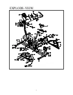
Page 3: ...2 EXPLODE VIEW I...
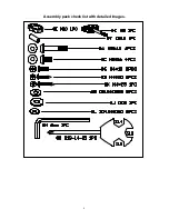
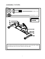
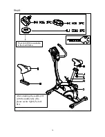
Page 5: ...4 Assembly pack check list with detailed images...
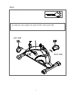
Page 7: ...6 Step 2 RIGHT SIDE LEFT SIDE According the picture tighten the pedal 10L R with wrench M...
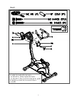
Page 9: ...8 Step 4 Attach the computer with G screws...
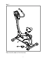
Page 12: ...11 Step 7 Please insert the adaptor 47 into the socket...


