background image


31 


GOLD 2.0


10.  PARTS LIST 

No. 

Description 

Spec 

Qty. 

No. 

Description 

Spec 

Qty. 

Main frame 


38 

Circle plug B 


Base frame 


39 

Foot pad 


Left upright 


40 

Small tube bushing 


Right upright  


41 

Adjustable wheel 


Incline motor bracket 


42 

Cone-shape cushion pad 


Computer bracket 


43 

Transportation wheel 


Adjustable tube bracket 


44 

Drive belt 


Adjustable bar 


45 

EVA pad 


Stiffened tube for running 

board 


46 

Running board 


10 

Front roller 


47 

DC motor group 


11 

Rear roller 


48 

Incline motor 


12 

Casing pipe 


49 

Control circuit board 


13 

Cylinder 


50 

Hand pulse with speed button 


14 

Roll casing pipe 


51 

Hand pulse with incline 

button 


15 

Flexible pin 


52 

Computer up wire 


16 

Allen wrench 

S=13

14

15 

53 

Computer bottom wire 


17 

6#Allen wrench 

6mm 

54 

Screw 

ST4.2*19 

18 

Computer bottom cover 


55 

Safety key 


19 

Computer panel 


56 

Light sensor 


20 

Left handrail 


57 

Transformer 


21 

Right handrail 


58 

Magnetic Ring 


22 

Left base cover 


59 

AC Single line 


23 

Right base cover 


60 

Blue single line 


24 

Motor cover 


61 

Brown single line 


25 

Side rail 


62 

Square rocker switch 


26 

Left back end cover 


63 

Standard power wire 


27 

Right back end cover 


64 

Overload protector 


28 

Bottom plate 


65 

I type hexagon nuts  

M10 

29 

Acrylic plate 


66 

I type hexagon nuts  

M8 

10 

30 

Foot pad for side rail 


67 

I type hexagon nuts 

M6 

31 

Long cushion pad 1 


68 

Hexagon bolt 

M10*80 

32 

Long cushion pad 2 


69 

Hexagon bolt 

M10*60 

33 

Cushion pad 


70 

Hexagon bolt 

M10*55 

34 

Roller wheel cover 


71 

Hexagon bolt 

M10*45 

Summary of Contents for GOLD 2.0

Page 1: ...uals are available through our website at www lifespanfitness com au Product may vary slightly from the item pictured due to model upgrades Read all instructions carefully before using this product Retain this owner s manual for future reference GOLD 2 0 OWNER S MANUAL ...

Page 2: ...RUCTIONS 3 2 IMPORTANT ELECTRICAL INFORMATION 4 3 IMPORTANT OPERATING INSTRUCTIONS 5 4 ASSEMBLY INSTRUCTIONS 6 5 FOLDING INSTRUCTIONS 10 6 OPERATION GUIDE 11 7 EXERCISE GUIDE 20 8 MAINTENANCE GUIDE 22 9 EXPLODED DIAGRAM 30 10 PARTS LIST 31 11 WARRANTY 33 ...

Page 3: ... or shag carpet Damage to both carpet and treadmill may result Do not block the rear of the treadmill Provide a minimum of 1 metre clearance between the rear of the treadmill and any fixed object Place your unit on a solid level surface when in use Never allow children on or near the treadmill When running make sure the plastic clip is fastened on your clothing It is for your safety should you fal...

Page 4: ...e Allowed temperature 5 to 40 degrees Remove the safety key after use to prevent unauthorized treadmill operation 2 IMPORTANT ELECTRICAL INFORMATION WARNING NEVER use a ground fault circuit interrupt GFCI wall outlet with this treadmill Route the power cord away from any moving part of the treadmill including the elevation mechanism and transport wheels NEVER remove any cover without first disconn...

Page 5: ...ntre of the belt which may result in serious injury In order to prevent losing balance and suffering unexpected injury NEVER mount or dismount the treadmill while the belt is moving This unit starts with at a very low speed Simply standing on the belt during slow acceleration is proper after you have learned to operate this machine Always hold on to handrail while making control changes A safety k...

Page 6: ... 68 I type hexagon nuts M8 2 70 Lock washer 8 8 45 Safety key 1 72 Screw M8 20 8 11 Allen Wrench S 13 14 15 1 73 Screw ST4 2 19 4 12 5 Allen Wrench 5mm 1 74 Screw M8 55 4 13 6 Allen Wrench 6mm 1 109 MP3 wire 1 61 Left base cover 1 ASSEMBLY TOOLS 6 Allen Wrench 5mm 1pc Wrench screw Driver S 13 14 15 1pc Note Do not connect power before completing assembly ...

Page 7: ...n Frame onto level ground 1 Move the display in the direction of the arrow in the diagram 2 Do not damage the wire inside the right upright 4 to the wire 3 Use 5 Allen Wrench Screw M8 20 72 and Lock washer 70 to secure Computer components 5 to the right upright 4 Repeat this for the left side ...

Page 8: ...ght Tubes in the direction of the arrows Support the upright tubes with your hands to prevent them from falling down 1 Use the 5 Allen wrench 12 to secure the right base frame with M8 55 bolt 71 and lock washer 70 Repeat this for the left side ...

Page 9: ...9 GOLD 2 0 STEP 5 STEP 6 1 Using the Allen Wrench 11 attach left right base cover 61 62 with screw ST4 2 19 73 1 Tighten all the screw then put safety key 45 on the computer ...

Page 10: ...B is locked into the round tube 1 Whilst supporting position A with your hand pull out the pin B with your right hand 2 Maintain this pin position whilst gently pulling the base frame towards the ground Let the base frame descend slowly to the ground 3 The base frame will descend automatically Please keep people and any pets away the machine during descent ...

Page 11: ...m TIME Shows time in h min DISTANCE Shows distance in km h CAL Shows calories in KCAL LAPS Shows 400m laps MATRIX CHART Rotates between speed and incline when in program mode TRACK Simulated 400m running track visible when in manual mode INCLINE Shows incline level SPEED Shows speed in km h ...

Page 12: ...tion Sets parameter when stopped SPEED 5 8 12 15 Instant speed adjustment buttons INCLINE Incline adjustment up and down Adjusts the incline gradient during operation Sets parameter when stopped INCLINE 3 6 9 12 Instant incline adjustment buttons Speaker mute button Fan function switch button Turns fan on off Left handlebar keys Incline adjustment buttons Right handlebar keys Speed adjustment butt...

Page 13: ...admill will enter the next section automatically Speed and incline will also be automatically adjusted to this section s parameter After all sections are complete the program will end and the treadmill will stop smoothly Press SPEED and INCLINE arrow buttons to adjust speed and incline gradient during the workout When the program enters the next section it will adjust to the default program automa...

Page 14: ...240 CM Weight 70KG 20 160KG 7 Heart rate test Hold the hand pulse sensors and the window will show your heartbeat after 5 seconds In order to achieve the most accurate heart rate reading please perform this test when the machine stopped and holding the sensors for no less than 30 seconds This data is only for reference and not to be used for medical purposes 8 Safety function If the safety key is ...

Page 15: ... 6 7 4 4 4 2 3 4 4 2 P9 INCLINE 5 5 5 6 6 6 4 4 6 6 5 5 8 8 9 9 9 7 4 2 SPEED 2 4 4 7 7 4 7 8 4 8 9 9 4 4 4 5 6 3 3 2 P10 INCLINE 5 6 6 6 7 5 8 8 4 4 4 5 5 8 8 10 10 8 6 3 SPEED 2 4 5 6 7 5 4 6 8 8 6 6 5 4 4 2 4 4 3 3 P11 INCLINE 4 5 3 2 6 6 2 2 2 2 2 4 5 6 3 2 5 5 2 0 SPEED 2 5 8 10 7 7 10 10 7 7 10 10 6 6 9 9 5 5 4 3 P12 INCLINE 1 2 3 2 3 5 5 0 0 2 3 5 7 3 3 5 6 5 3 3 SPEED 3 4 9 9 5 9 5 8 5 9 7...

Page 16: ...1 9 7 5 3 SPEED 2 4 6 2 4 6 2 4 6 2 2 4 6 2 4 6 2 4 6 2 P31 INCLINE 2 5 6 8 10 8 6 6 2 2 2 5 6 8 10 8 6 6 2 2 SPEED 1 3 4 5 6 5 4 3 2 1 1 3 4 5 6 5 4 3 2 1 P32 INCLINE 2 4 4 5 2 3 4 5 4 3 2 4 4 5 2 3 4 5 4 3 SPEED 1 4 6 8 6 6 4 4 2 2 1 4 6 8 6 6 4 4 2 2 P33 INCLINE 2 3 6 2 4 6 2 4 6 2 2 3 6 2 4 6 2 4 6 2 SPEED 1 4 6 8 10 8 6 4 2 2 1 4 6 8 10 8 6 4 2 2 P34 INCLINE 4 5 5 5 6 6 6 7 8 9 9 9 10 10 10 1...

Page 17: ... 1 1 3 3 2 2 2 SPEED 2 3 3 4 5 3 4 5 5 3 4 5 4 4 4 2 3 3 5 3 P52 INCLINE 1 2 2 2 2 3 3 2 2 2 2 2 3 3 3 4 4 3 2 2 SPEED 2 4 4 5 6 4 6 6 6 4 5 6 4 4 4 2 2 5 4 2 P53 INCLINE 2 3 3 2 2 3 3 3 2 2 2 2 4 4 4 6 6 3 2 2 SPEED 2 4 4 6 6 4 7 7 7 4 7 7 4 4 4 2 4 5 3 2 P54 INCLINE 2 3 3 2 2 3 3 3 2 2 2 2 4 4 4 6 6 3 2 2 SPEED 3 5 5 6 7 7 5 7 7 8 8 5 9 5 5 6 6 4 4 3 P55 INCLINE 3 3 3 4 4 5 5 5 4 4 4 4 5 5 3 3 3...

Page 18: ...1 1 1 1 SPEED 1 2 6 6 8 10 6 6 2 2 1 2 6 6 8 10 6 6 2 2 P73 INCLINE 1 1 1 1 1 1 1 1 1 1 1 1 1 1 1 1 1 1 1 1 SPEED 1 3 4 5 2 3 4 5 3 2 1 3 4 5 2 3 4 5 3 2 P74 INCLINE 1 1 1 1 1 1 1 1 1 1 1 1 1 1 1 1 1 1 1 1 SPEED 1 4 6 2 4 6 2 4 6 2 1 4 6 2 4 6 2 4 6 2 P75 INCLINE 2 6 6 8 10 8 6 6 2 2 2 6 6 8 10 8 6 6 2 2 SPEED 2 3 4 5 6 5 4 3 2 1 2 3 4 5 6 5 4 3 2 1 P76 INCLINE 2 3 4 5 2 3 4 5 4 3 2 3 4 5 2 3 4 5 ...

Page 19: ...6 6 2 2 P91 INCLINE 1 2 2 3 4 4 3 2 1 0 1 2 2 3 4 4 3 2 1 1 SPEED 2 3 4 5 2 3 4 5 3 2 2 3 4 5 2 3 4 5 3 2 P92 INCLINE 1 4 5 7 9 11 9 7 5 3 1 4 5 7 9 11 9 7 5 3 SPEED 2 4 6 2 4 6 2 4 6 2 2 4 6 2 4 6 2 4 6 2 P93 INCLINE 2 5 6 8 10 8 6 6 2 2 2 5 6 8 10 8 6 6 2 2 SPEED 1 3 4 5 6 5 4 3 2 1 1 3 4 5 6 5 4 3 2 1 P94 INCLINE 2 4 4 5 2 3 4 5 4 3 2 4 4 5 2 3 4 5 4 3 SPEED 1 4 6 8 6 6 4 4 2 2 1 4 6 8 6 6 4 4 ...

Page 20: ...fitness and reduce the effect of aging and stress The key to success is to make exercise a regular and enjoyable part of your everyday life The condition of your heart and lungs and how efficient they are in delivering oxygen via your blood to your muscles is an important factor to your fitness Your muscles use this oxygen to provide enough energy for daily activity This is called aerobic activity...

Page 21: ...inutes of stretching to cool down This will increase the flexibility of your muscles and will help prevent post exercise problems Workout Guidelines TARGET ZONE THIS IS HOW YOUR PULSE SHOULD BEHAVE DURING GENERAL FITNESS EXERCISE REMEMBER TO WARM UP AND COOL DOWN FOR A FEW MINUTES The most important factor here is the amount of effort you put in The harder and longer you work the more calories you...

Page 22: ...ORE MAINTENANCE WARNING STOP TREADMILL BEFORE FOLDING 1 General Cleaning Use a soft damp cloth to wipe the edge of the belt and the area between the belt edge and frame A mild soap and water solution along with a nylon scrub brush will clean the top of the textured belt This task should be done once a month Allow to dry before using On a monthly basis vacuum underneath your treadmill to prevent du...

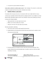
Page 23: ...e deck according to the following timetable o Light use less than 3 hours per week every 6 months o Medium use 3 5 hours a week every 3 months o Heavy use more than 5 hours per week every 6 8 weeks See below procedures for lubricating 1 Use a soft dry cloth to wipe the area between the belt and deck 2 Spread lubricant onto the inside surface of belt and deck evenly make sure the machine is turned ...

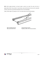
Page 24: ...ition 3 Feel the underside surface of the running mat If the surface is slick when touched then no further lubrication is needed If the surface is dry to the touch apply a suitable silicone lubricant We recommend that you use a silicone based spray to lubricate your Lifespan treadmill This can be purchased directly from us or any hardware store ...

Page 25: ...ully turn the right adjusting bolt anticlockwise until the belt centers If the belt has drifted to the left Whilst the treadmill is running at 4km h carefully turn the left adjusting bolt 1 4 turn clockwise Then monitor treadmill until the belt centers Repeat until the belt correctly centers See Picture B If you have over adjusted it carefully turn the left adjusting bolt anticlockwise and until t...

Page 26: ...nce and not all treadmills are the same Some treadmills that have longer belts may give different measurements for correct belt tightness Simply if the belt begins to slip during use this is an indication that the belt still needs tightening Video Tutorial Available at http youtu be vllsamTSvvA Lifespan Fitness Channel http www youtube com user treadmillsvideos ...

Page 27: ...that you check your motor every 1000 hours of usage IMPORTANT Before beginning the replacement of your motor brush ensure that the treadmill is off and unplugged from the electrical socket 1 Remove the cover from the motor by squeezing it from the sides 2 You ll find the motor brush held in with a clip with the lead plugged in 3 Pull the clip out from its position 4a Hold the clip out of the way w...

Page 28: ...n in which it was originally placed and put it safely aside 5 Slide the motor brush out from its slot If the brush is shorter than 2cm on the longest side you will need to replace both brushes 6 Slide the motor brush lead off the terminal using a another small screwdriver or needle nosed pliers 7 Plug the new motor brush lead into the terminal 8 Slide the new motor brush into the slot ...

Page 29: ...tor brush is held firmly in place by the clip and that the lead is plugged securely onto the terminal 11 Replace the motor cover Repeat steps 1 15 for the second brush located on the opposing side of the motor 12 You have now successfully replaced the motor brushes We also recommend that you remove any dirt and dust from your treadmill motor fan using a vacuum cleaner before replacing the cover ...

Page 30: ...30 GOLD 2 0 9 EXPLODED DIAGRAM ...

Page 31: ...pin 1 52 Computer up wire 1 16 Allen wrench S 13 14 15 1 53 Computer bottom wire 1 17 6 Allen wrench 6mm 1 54 Screw ST4 2 19 4 18 Computer bottom cover 1 55 Safety key 1 19 Computer panel 1 56 Light sensor 1 20 Left handrail 1 57 Transformer 1 21 Right handrail 1 58 Magnetic Ring 1 22 Left base cover 1 59 AC Single line 1 23 Right base cover 1 60 Blue single line 1 24 Motor cover 1 61 Brown single...

Page 32: ...d screws ST4 8 19 4 77 Hexagon bolt M8 48 3 88 pan head screws ST4 2 15 18 78 Hexagon bolt M8 40 2 89 Screw ST4 2 12 26 79 Hexagon bolt M8 25 2 90 Flat washer 10 7 80 pan head screw M6 45 2 91 Lock washer 10 20 81 Hexagon screw M6 25 6 92 Spring lock washer 10 4 82 pan head screw ST4 2 15 4 93 Lock washer 8 13 83 pan head screw M5 8 4 94 Lock washer 6 9 84 pan head tapping screws ST4 2 80 4 95 pan...

Page 33: ...are entitled to have the goods repaired or replaced if the goods fail to be of acceptable quality and the failure does not amount to a major failure Full details of your consumer rights may be found at www consumerlaw gov au Please visit our website to view our full warranty terms and conditions http www lifespanfitness com au warranty repairs Warranty and Support Please email us at support lifesp...

Page 34: ...ensor signal 1 Check that all sensor wires are in good condition replace if damaged 2 Check the speed sensor replace if damaged 3 Check the motor condition and wiring E05 Current overload protection 1 Over rated loaded or the motor is stuck causing excessive current machine will start self protection system Adjust the machine and restart 2 Check if there is irregular noise coming from the motor or...

Page 35: ...t rate changes Too much noise will create an incorrect reading Medical conditions or having no electrical signal in the hands are other factors that may affect pulse readings as well These are limitations of hand pulse technology and even the most expensive systems which can cost upwards of 3 000 used in hospitals have the same problems The difference is that a patient in a hospital is not running...

Reviews: