9
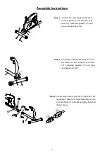
Step 6:
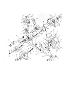
connect inductive connection wire (79a) with
sensor wire (42a) and inductive connection
wires 79 b and c to sensor wires (47) a, b as
shown below. Insert the handle upright (3) on
the main frame (1) and lock the upright in place
with 4-inner hexagon cheese-head bolts (16)
and cambered gaskets (30).
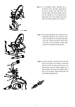
Step 4:
The backboard frame assembly (4) is
connected to the rear frame assembly (2)
by 4-inner hexagon pan head bolts (16).
The seat cushion (18) and the back cushion
(19) are attached to the backboard frame
respectively by 4-inner hexagon pan head
bolts (16) and the gaskets (17) as shown
Step 5:
The armrest assembly (9) is attached to the
backboard assembly (4) by 2-square neck
bolts (20), gaskets (17) and high cap-shaped
nuts (22). Connect hand pulse wires (15a)
and (15b) to their respective cables (25a)
and 25b) on the armrest assembly (9).
Summary of Contents for RC 80
Page 1: ...RC 80 Owner s Manual ...
Page 3: ......


