background image

——————————

SPING BIKE

—————————


——————————————————————

3

——————————————————————


2. ASSEMBLY INSTRUCTION: 


Step 1

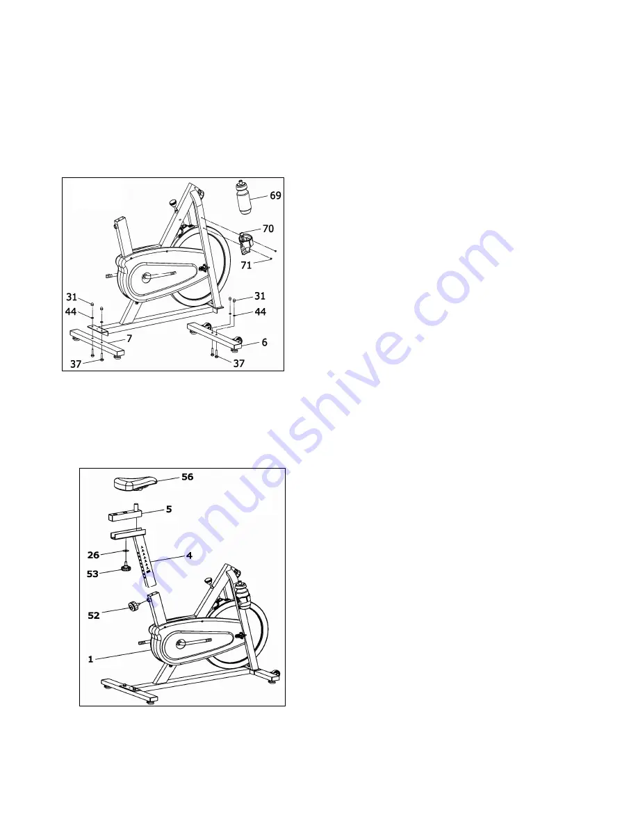
Assembly the Front Stabilizer and the Rear Stabilizer 


A: Attached bolt (No 37) to rear stabilizer, main frame 

(No 1) and flat washer (No 37), And use nut (No 31) 

to screw it . 


B. Attached front stabilizer (No 6) to main frame the 

same as A ways. 


C. Attached water bottle frame to main frame by nut 

(No  71),  and  put  water  bottle  in  the  water  bottle 

frame. 


Step 2: Assembly the seat 


A:  With  vertical  seat  post  (No  4)  inserting 

corresponding hole of the main frame (No 1) , select 

appropriate height.  And use  spring  adjustment  knob 

to screw it.                   


B:    Attached  seat  post  (No  4)  to  vertical  seat  post                                                                             

No  5)  with  flat  washer  (

)  (  No  26)  and  spring 

adjustment knob ( No 53)


C: With seat pad ( No 56) inserting vertical seat post   

(No 5), and screw under the nut and bolt of seat pad.   


FIG.1 

FIG.2 

Summary of Contents for SP250

Page 1: ...SP250 WARNING 1 IMPORTANT SAFETY NOTICE 1 ASSEMBLY INSTRUCTION 2 4 EXPLODED VIEW PARTS LIST 5 8 EXERCISE INSTRUCTIONS 9 11...

Page 2: ...rson whose body weight exceeds this limit should not use this machine Locate a comfortable work site assemble your training bike in an open space with adequate ventilation and lighting Keep children a...

Page 3: ...should not use the training bike without the presence of a qualified health professional of physician Never operate this machine if it is not functioning properly When the user doesn t need to operat...

Page 4: ...r bottle frame to main frame by nut No 71 and put water bottle in the water bottle frame Step 2 Assembly the seat A With vertical seat post No 4 inserting corresponding hole of the main frame No 1 sel...

Page 5: ...42 flat washer No 44 and use bolt No 42 flat washer No 44 to lock console seat on the handle bar C Console back of the groove A No 68 insert into handle bar No 3 on the protruding piece B As chart FIG...

Page 6: ...pull the knob back Slide horizontal seat post into desired position Align holes and then retighten the adjusting knob C To adjust the handlebar height slacken the spring knob and secondary Knob and pu...

Page 7: ...SPING BIKE 6 EXPLODED VIEW...

Page 8: ...SPING BIKE 7...

Page 9: ...4 PRESS SLEEVEI 1 15 PRESS SLEEVEII 1 16 FLAT WASHER I 1 22 8 35 2 17 FLAT WASHER II 1 40 2 8 18 NUT 1 7 8 19 SEPARATED SETS OF BRAKE ROD 1 20 COMPRESSION SPRING 1 2 21 BRAKE LEVER SPRING 1 0 8 30 22...

Page 10: ...51 RIGHT PLASTIC COVER 1 52 SPRING ADJUSTMENT KNOB 2 53 SPRING ADJUSTMENT KNOB 1 54 END CAP 4 50 25 55 END CAP 2 56 SEAT PAD 1 57 ADJUSTABLE FOOT PAD 4 58 END CAP 2 38 38 1 5 59 LEFT PEDAL L 1 60 RIGH...

Page 11: ...to do a few stretching exercises as shown below Each stretch should be held for approximately 30 seconds do not force or jerk your muscles into a stretch if it hurts STOP 2 The Exercise Phase This is...

Page 12: ...rds the end of the exercise phase you should increase resistance making your legs work harden than normal You may have to reduce your speed to keep your heart rate in the target zone The important fac...

Reviews: