——————————
SPING BIKE
—————————
——————————————————————
(
4
)
——————————————————————
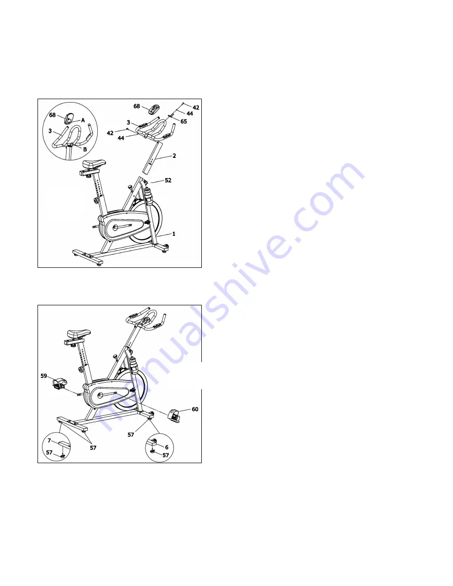
Step 3: Assembly the handlebar post
A: Unscrew the spring adjustment knob (No 52)
of the main frame( No 1), and handle post inset
(No 2) in hole of the main frame, select
appropriate height, and screw spring adjustment
knob (No 52).
B. Attached handle bar (No 3) to handle post (No
2) with bolt (No 42), flat washer (No 44) , and use
bolt (No 42), flat washer (No 44) to lock console
seat on the handle bar.
C. Console back of the groove A ( No 68) insert
into handle bar (No 3) on the protruding piece B
(As chart FIG3). The induction line and console
behind the wire connection, pulse cable insert
into hole of back console.
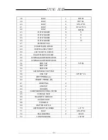
Step 4: Assembly the Pedals
A. The left pedal (No 59) screwing in left brace
(the position is left when you sit on the spin bike)
B. And the right pedal (No 59) screwing in right
brace
FIG.3
FIG.4
Summary of Contents for SP250
Page 7: ...SPING BIKE 6 EXPLODED VIEW...
Page 8: ...SPING BIKE 7...


