27
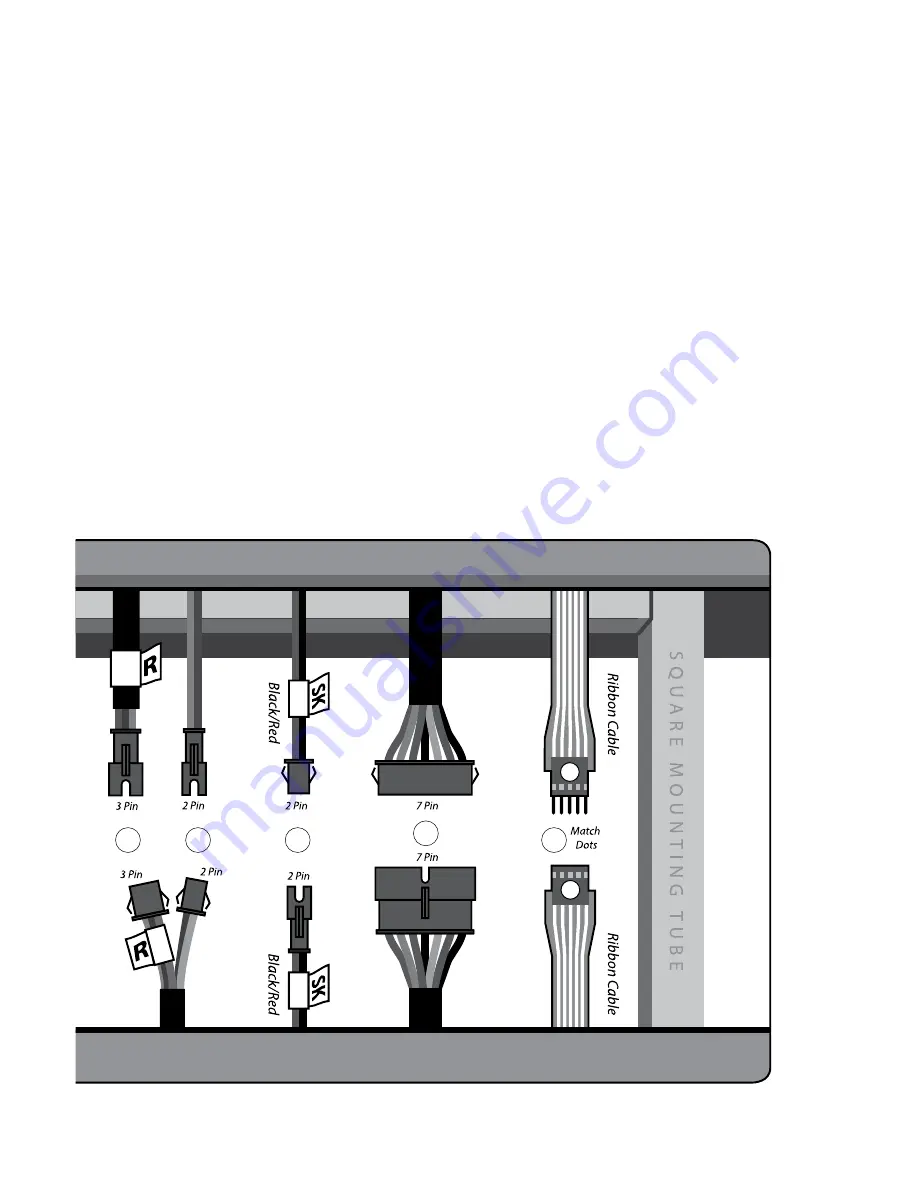
C. Securely attach the seven remaining cable connectors – There are
four 2-pin, two 3-pin and one 7-pin connector that will need to be
connected.
1. Attach the 7-pin connectors together (C1) .
2. Attach the wires labeled “SK” together (C2).
3. Attach the White 2-pin connector wires together (C3).
4. Next, attach the two 3-pin connectors (C4) together. There are labels
on these that say L and R. Connect the L to L and the R to R. These
are for the handlebar speed and incline switches.
5. The remaining two 2-pin connectors are for the contact heart rate
sensors and it doesn’t matter which gets plugged into the other.
D. Carefully tuck all wires into the bottom or top console housing.
5B
C5
C2
C4
Assembling Your Treadmill
C1
Summary of Contents for TR2000e
Page 1: ...TR5000i Light Commercial Treadmill Owner s Manual ...
Page 2: ......
Page 4: ...2 ...
Page 6: ...4 ...
Page 13: ...11 About Your Treadmill Built in Speakers Readout Display Media Holders Operating Keyboard ...
Page 52: ......
Page 53: ......


