background image

22 

LSC

User’s Manual.

m

       CAUTION

The voltage indicator also serves as a ”fault indicator” for the wheelchair’s electronic system.  

* See page 82-83 for more information.

2.4 

Battery Voltage Indicator

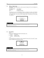
The battery voltage indicator lets you know how much charge is left in your batteries(from  

left to right):
Red+Green 

= Fully charged

Red+Yellow 


= Half charged

Red    


= Charge the batteries

The best way for you to use the indicator is to learn how it behaves as youdrive your wheelchair. 

Like the fuel gauge in a car, it is not completely accurate, but will help you avoid running out of ”fuel”.
The  indicator  gives  you  a  more  accurate  reading  about  a  minute  after  you  start  driving  

the wheelchair.

m

       CAUTION

The speed display also serves as a ”fault indicator” for the wheelchair’s electronic system. * 

See page 82-83 for more information

2.5 

Speed display

Speed

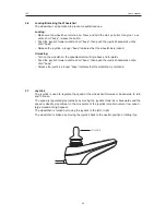
Indicates the adjusted speed at which the wheelchair


is


set.

1 - 2 lamps 

= Low speed 

3 - 4 lamps 

= Medium speed 

     5 lamps 

= Maximum speed

Profile

In special aplications the wheelchair can be programmed with more then one profile. In these 

cases, the display shows the selected profile.

Summary of Contents for LSC

Page 1: ...User s Manual LSC Power Stand Up Wheelchair ...

Page 2: ......

Page 3: ... sales in the area where you live For the United Kingdom Permobil UK Oceanic Ground Floor Navigation Business Park Waters Meeting Road Bolton BL1 8SW Tel 44 0 1484 722 888 Fax 44 0 1484 723 013 E mail info permobil co uk For all other countries LifeStand France SAS 5 Rue Clément Ader 69740 Genas France Tel 33 0 4 37 26 27 28 Fax 33 0 4 37 26 27 29 Email info permobil fr ...

Page 4: ......

Page 5: ...n 14 Operating Instructions 15 1 Adjusting and switching on 15 2 VR2 Control Panel 20 3 R Net control panel LCD color display 24 4 Handling 30 5 Standing position and adjusting the seat back 32 6 Batteries and Maintenance 33 Accessories 38 Technical Specifications 39 Cabling Overview 40 ...

Page 6: ...ossible problems that can arise while operating this wheelchair Always keep these operating instructions handy since the need for important information can arise con cerning its use safety and maintenance It is also possible to obtain information concerning our products from our home page on the Internet You can find us at www permobil com All information pictures illustrations and specifications ...

Page 7: ...e Here is the needed contact information and a guidance document in what information we need to investigate the incident Complete the information as much as possible This is of great help for us To increase the product quality and to ensure that our product is safe through the whole life cycle we need you to send in Incident Reports It is also stated in MEDDEV 2 12 1 and Annex 9 that the manufactu...

Page 8: ...ermobil is not responsible for personal injuries or property damage resulting from any person s failure to follow the warnings and instructions in this manual Permobil is not responsible for injuries or dam age resulting from failure to exercise good judgment The final selection and purchasing decision about the type of wheelchair to be used is the responsibility of the wheelchair user and his or ...

Page 9: ...chair while it was being shipped to you you should check the following items before beginning to use it that all products ordered are included in the delivery incuding operating instructions and pos sible other documentation If you suspect that something is missing then contact your supplier or Permobil for more information as soon as possible that no transport related or other damages have occurr...

Page 10: ...ical limitations or use of medication either prescribed or over the counter may limit your ability to operate your wheelchair safely Be sure to consult with your physician about your physical limitations and medications m CAUTION Modifications Any unauthorized modifications to the wheelchair may increase the risk of personal injury and prop erty damage including damage to the wheelchair All modifi...

Page 11: ...ls can be elevated off of the ground by the attendant stepping on the Anti Tip tube on the rear of the chair and simultaneously pulling back and down on the Push Handles While it is not recommended that the chair be tipped back any further the Anti Tip wheels hitting the floor it is pos sible This would be done by rotating the Anti Tip tubes to the up position see page 19 Make certain to return th...

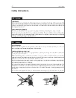
Page 12: ... protect you in an acci dent You may even receive further injury from the belts Transfer into and out of the chair Be sure that the wheel locks are engaged before entering or leaving the wheelchair and before pivoting the arm for transfer When transferring into or out of the wheelchair every precaution should be taken to reduce the distance between the wheelchair and the place to which the user is...

Page 13: ... injury from the belts m WARNING Maintenance and Service Carry out only the service and maintenance which are stated in the User s Manual All other service and maintenance must be performed by a qualified service technician authorized by Permobil to per form such service on Permobil products Do not use parts or accessories not authorized by Permobil Use of unapproved aftermarket acces sories and p...

Page 14: ... wheelchair It is also rec ommended that it be serviced annually by an authorized Permobil dealer 4 Benefits of a Daily Standing Regimen The use of any stand up device should be done only under the prescription and supervision of a medi cal professional At the outset it is recommended that your introduction to regular standing be closely monitored by your Physical or Occupational Therapist It has ...

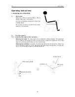
Page 15: ...ion Adjusting the height The tibia supports can be adjusted to different heights This adjustment can be made by unscrewing the bolt in the tibia supports Ideally the greater part of the tibia support should be approximately 4 cm below the kneecap Adjusting the inclination The holes in the tibia supports are fixed to the footrest cheeks by 2 screws With the eccentric nut in the oblong hole and depe...

Page 16: ...ne The left side has to be placed first to bolt the right side in the hook If you can see the green part of the button this indicates that the support is correctly locked The tibia supports MUST be correctly locked before standing up To release the supports Press the red button Swivel the right side The left side has a passive safety system To remove lift it up nearly 2cm and then swivel towards t...

Page 17: ...them at the required height Replace the upper part 3 straps with the lower part 2 straps and vice versa 1 3 2 Adjusting the armrest depth The depth of the armrests can be adjusted by 8 cm 3 To do this turn the armrest over Two hexagon socket screws allow the depth to be adjusted Try the armrests in the chest support position Slide the armrests until properly adjusted Return them to the armrest pos...

Page 18: ...to the hole indicated in the following table Adjust the upper part first then the lower part in the same way For example if hole n 1 is given for the upper part in the table select hole n 1 for the lower seat bar Top seat bar Bottom seat bar Top seat bar Hole n 1 Thigh length Seat depth Hole n Kid model 44 33 1 46 35 2 48 37 3 50 39 4 Adult model 52 41 5 54 43 6 56 45 7 58 47 8 60 49 9 62 51 10 64...

Page 19: ...es fully extended refer to Preparation for moving into the standing position The chair is properly adjusted if the line from the hips to ankles passing through the knees is perfectly straight If it is not the person should be seated once more and the adjustment fine tuned by retracting first the seat back assembly and then the tibia supports ...

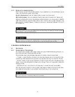
Page 20: ...evice Connection of other electrical devices may damage the control system or affect the E M C performance of the wheelchair m WARNING The wheelchair s warranty will be voided if any device other than a battery charger supplied with the wheelchair or the lock key is connected into the control panels charger socket Charging socket Charging plug Connect he charging plug with the guide upwards 2 VR2 ...

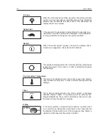
Page 21: ...to operate m WARNING Do not use the Power Switch Button to stop the wheelchair unless there is an emergency If you do you may get thrown out of the chair or shorten the life of the wheelchair drive components Warning Horn Press the button to sound the horn and attract attention Speed Buttons These buttons decreases increases the maximum speed setting In special applications these buttons could all...

Page 22: ...ive your wheelchair Like the fuel gauge in a car it is not completely accurate but will help you avoid running out of fuel The indicator gives you a more accurate reading about a minute after you start driving the wheelchair m CAUTION The speed display also serves as a fault indicator for the wheelchair s electronic system See page 82 83 for more information 2 5 Speed display Speed Indicates the a...

Page 23: ...ion or letting it go 2 6 Locking Unlocking the Wheelchair The wheelchair can be locked to prevent unauthorized use Locking Make sure the wheelchair is turned on Press and hold the start up button for aprox 1 sec until a short beep release the button Push the joystich forward untill a short beep then push the joystick backwards until a short beep Release the joystick a longer beep indicates that th...

Page 24: ...wheelchair may also be equipped with a Seat Control Panel in addition to the control panel 3 2 Function Buttons On the control panel there are a total of 10 Function Buttons PROFILE MODE On Off Speedbuttons Decrease Increase Mode Hazard Button LED Left Indicator Button LED Horn Button Profile Button Lights Button LED Right Indicator Button LED Only active if the wheelchair is equipped with lights ...

Page 25: ...hts This function is used when the wheelchair is positioned in a way making it a obstruction for others Push the button to activate the hazard lights and push it again to deactivate them When activated the indicator LED will flash in sync with the wheelchair s indicators Lights Button and LED This button activates and deactivates the wheelchair s lights Depress the button to turn the lights on and...

Page 26: ...that all is well Flashing Slowly The control system is functioning correctly but you should charge the battery as soon as possible Stepping Up The wheelchair batteries are being charged You will not be able to drive the wheelchair until the charger is disconnected and you have switched the control system off and on again Current profile Profile name Battery indicator Max Speed indicator Clock Spee...

Page 27: ...his symbol is displayed when the control system has intentionally reduced the power to the motors in order to protect them against heat damage Control system Temperature This symbol is displayed when the control system has intentio nally reduced its own power in order to protect itself against heat damage Timer This symbol is displayed when the control system is changing between different states A...

Page 28: ...he menu and then moving the joystick to the right Setting the time Set Time Select Set Time in the menu Move the joystick to the right to go to the menu for setting the time Then select Year Month Date Hours and Minutes by moving the joystick left or right Set the desired value by moving the joystick up or down Exit the installation menu by selecting Exit and then moving the joystick up or down Di...

Page 29: ...ground in the menu Move the joystick right or left to select Blue White or Auto Blue Blue The display background is blue in all profiles White White The display background is white in all profiles Automatic Auto The display background is programmed in the various travel profiles E g blue background for slow profile for indoors travel and white background for rapid pro file for outdoors travel Diag...

Page 30: ...hat may be shown in the display Which icons are shown varies depending on the seat model and available functions 3 6 Joystick The joystick is used to regulate the speed of the wheelchair forwards or backwards to turn and to brake The speed is regulated proportionally by moving the joystick forwards or backwards and the speed is directly proportional to the movement of the joystick small movement l...

Page 31: ...oystick 4 2 Driving your chair The direction of the chair depends on the direc tion given to the joystick Push forward The wheelchair drives straight forward Push to the right The wheelchair drives to the right Push left The wheelchair drives to the left Push backwards The wheelchair will drive straight backwards 4 3 Braking The system automatically returns to the neutral position when you let go ...

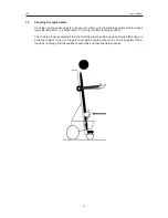
Page 32: ...unctions back rest recline standing position On the display the blinking part of the wheelchair diagram display indicates the activated function With the joystick you can select by a lateral pressure to the left to the right the icon back recline or standing position VR2 Control System Press the left Seat Function button to activate the standing up mode Press the right Seat Function button to acti...

Page 33: ...ng obstacles never drive on a slope Do not attempt to move or be moved standing in freewheel mode 6 Batteries and Maintenance 6 1 The batteries 6 1 1 Characteristics of the Batteries Your wheelchair is equipped with sealed maintenance free TRACTION batteries that are con form to the air transport standards DOT and IATA These batteries have been developed especially for traction of electric wheelch...

Page 34: ... depends partly on the number of cycles dis charge charge but also on the level of every discharge Thus a battery discharged 100 is limited to a number of 200 cycles while the same battery discharged to only 75 has a number of 275 cycles and still the same battery dis charged to only 50 has a even higher number of 450 cycles This displays the charge available in the battery and can be used to aler...

Page 35: ...emselves naturally and loose continuously their capacity In case the chair isn t being used for a long period of time it is recommended to charge it at least once a month to maintain a complete level of charge Good to know New batteries need a start up time of 15 to 20 charging cycles before they reach their full capacity 6 1 3 Use of the charger Use only the charger provided with the wheelchair I...

Page 36: ...ment by recycling this product in a recycling centre at the end of its lifespan m WARNING 6 2 Batteries The space required for carrying the chair in a vehicle can be greatly reduced by a Removing the tibia supports and folding the footrest b Folding the backrest down c Removing the control unit from the wheelchair m CAUTION Except specially equipped vehicle your wheelchair has neither been designe...

Page 37: ...Check the motors cables and connections to the control system 1505 Left brake error Check the solenoid cables and connections to the control system 1506 Right brake error Check the solenoid cables and connections to the control system Low battery Low battery Check The condition of the batteries and the connections to the control system High battery High battery voltage Check the condition of the b...

Page 38: ...o enable a return to the sitting position The procedure is as follows remove the rear plastic bonnet unplug the jack from the stand up gas cylinder plug the jack into the jack socket which forms one piece with the right hand battery tray the gas cylinder automatically initiates a slow descent into the sitting position once the position is reached unplug the jack and contact your distributor if thi...

Page 39: ... x 50 8 Rear 350 3 00 8 Brakes Manual by pushing and electromagnetic in the wheels Tibia supports Adjustable in height in inclination and in width Propulsion Electric Rear stabilisation By two anti tip rollers with variable symmetry Range approximately 25 km Maximum speed 7 km h User s maximum weight 120 kg Maximum gradient 9 with 80 kg load 6 with 120 kg load Batteries 4 x 12 Volt 18 Ah Charging ...

Page 40: ...40 LSC User s Manual ...

Page 41: ......

Page 42: ......

Page 43: ......

Page 44: ...Order no 205265 UK 0 ...

Reviews: