background image

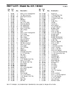
PART LIST—Model No. 831.159460

R0696A

Key Part

No.

No.

Qty.

Description

1

100291

3

5/16” x 2 1/2” Carriage Bolt

2

012139

3

1/4” Nylon Locknut

3

012056

23

5/16” Nylon Locknut

4

127049

1

Base

5

127050

1

Stabilizer

6

115164

3

“V”-Pulley

7

013581

3

3/8” x 2 1/2” Bolt

8

014073

8

5/16” Flat Washer

9

014132

4

3/8” Flat Washer

10 014063

12

1/4” Flat Washer

11 119377

6

5/16” x 2 3/4” Bolt

12 013601

3

3/8” x 2” Bolt

13 126875

1

Seat

14 123385

3

5/16” x 2 3/4” Carriage Bolt

15 115370

7

3 1/2” Pulley

16 120003

1

3/8” x 3 1/2” Bolt

17 127051

1

Press Frame

18 127937

6

1/4” x 1/2” Screw

19 122690

2

Weight Bumper

20 127052

1

Pulley Bracket

21 012149

12

3/8” Nylon Locknut

22 128275

4

5/16” x 2 1/2” Bolt

23 127064

1

Long Cable

24 128276

5

1/4” x 2” Screw

25 127505

8

Weight

26 122693

1

Weight Pin

27 108874

2

2” Square Inner Cap

28 127065

2

12 1/2” Pad Tube

29 127053

1

Leg Lever

30 127066

4

5 1/2” Pad

31 119702

6

Hand Grip

32 103833

5

1 1/2” Square Inner Cap

33 121421

1

5/16” x 2 1/4” Bolt

34 119170

4

3/4” Round Inner Cap

35

127067

1

Short Cable

36 127054

1

Seat Frame

37 127055

1

Seat Plate

38 128281

1

1/4” x 2” Carriage Bolt

39 115177

1

Nylon Strap

40 119192

1

Seat Knob

41 127056

1

Backrest

42 127057

1

Front Upright

43 128283

4

1/4” x 2 1/2” Screw

44 113666

6

1 3/4” Square Inner Cap

45 127180

2

10” Pad

46 127058

2

Press Arm

47 127059

1

Left Arm

Key Part

No.

No.

Qty.

Description

48 127060

1

Right Arm

49 120733

10

1” Round Inner Cap

50 126799

3

Long Cable Trap

51 105723

2

2” Square Outer Cap

52 116868

1

Chain

53 103087

3

Cable Clip

54 127061

1

Lat Bar

55 127068

1

Top Frame

56 127069

1

Rear Upright

57 127070

1

Long “U”-Bracket

58 127071

1

Medium Cable

59 128292

1

3/8” x 8” Bolt

60 128293

1

5/16” x 6” Bolt

61 122688

2

1/2” x 3/4” Spacer

62 122719

2

Weight Guide

63 127167

1

Weight Tube

64 122691

1

Weight Tube Bumper

65 120696

1

1” Square Inner Cap

66 127168

5

Cable Trap

67 127169

1

Small “U”-Bracket

68 128297

1

5/16” x 5” Bolt

69 108778

4

1” Retainer

70 120808

2

1” Round Cover Cap

71 118588

4

3/8” x 3 3/4” Bolt

72 102073

1

5/16” x 1 3/4” Bolt

73 121845

1

5/8” x 9/16” Spacer

74 121828

2

1 1/4” x 2 1/2” Plastic Bushing

75 126891

2 1” x 

7/8” Plastic 

Bushing

76 127506

1

Top Weight

77 127170

1

VKR Backrest

78 127171

2

VKR Arm Rest

79 127172

1

Left VKR Arm

80 127173

1

Right VKR Arm

81 126145

2

5/16” x 3” Bolt

82 127175

1

Curl Pad

83 127517

1

Foot Rest

84 127176

1

Curl Frame

85 127177

1

Curl Knob

86 127178

1

Curl Bar

87 115648

1

1/2” x 1/2” Bushing

88 126883

1

Brace

89 013211

1

5/16” x 3/4” Bolt

90 013480

1

5/16” x 1 1/4” Carriage Bolt

91 130313

1

1/2” x 3/8” Bushing

92 124590

1

3 1/2” Low Pulley

#

127242

1

User’s Manual

#

127243

1

Exercise Guide

Note: “#” indicates a non-illustrated part. Specifications are subject to change without notice.

Summary of Contents for 831.159460

Page 1: ...precautions and instruc tions in this manual before using this equipment Save this manual for future reference PATENT PENDING The serial number can be found in the location shown below Write the seria...

Page 2: ...inning assembly FULL 90 DAY WARRANTY For 90 days from the date of purchase if failure occurs due to defect in material or workmanship in this SEARS WEIGHT SYSTEM EXERCISER contact the nearest SEARS Se...

Page 3: ...foot plate when perform ing an exercise that could cause the home gym system to tip 11 Never release the press arm butterfly arms leg lever lat bar or nylon strap while weights are raised The weights...

Page 4: ...e and strength or improve your cardiovascular system the SYSTEM 200 will help you to achieve the specific results you want For your benefit read this manual carefully before using the LIFESTYLER SYSTE...

Page 5: ...t FRAME ASSEMBLY 88 5 ASSEMBLY Before beginning assembly carefully read the following information and instructions Assembly requires two people Due to the size and weight of the SYSTEM 200 it should b...

Page 6: ...ss a 1 3 4 Square Inner Cap 44 into each end of the crossbar on the Top Frame Press two 1 Round Inner Caps 49 into the top of the crossbar Attach the Top Frame 55 to the Front Upright 42 and the Rear...

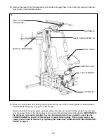
Page 7: ...h the 5 16 x 6 Bolt 60 two 1 2 x 3 4 Spacers 61 and a 5 16 Nylon Locknut 3 Be sure that the Pulley Bracket 20 is in front of the right Weight Guide 62 as shown 7 Press a 1 x 7 8 Plastic Bushing 75 ont...

Page 8: ...and a Long Cable Trap 50 to the Left Arm 47 in the same manner 10 Lubricate both axles on the Top Frame 55 Slide the Right Arm 48 onto the right axle Note Be careful not to confuse the Right Arm with...

Page 9: ...the ball is on the indicated side of the Pulley and that the Cable is between the Pulley and the hook Tighten the 3 8 x 3 3 4 Bolt 71 and the 3 8 Nylon Locknut not shown 13 Wrap the Long Cable 23 arou...

Page 10: ...Bracket 20 can move freely 17 See the inset drawing Attach a 3 1 2 Pulley 15 and a Cable Trap 66 to the indicated hole in the Long U Bracket 57 with a 3 8 x 2 Bolt 12 and a 3 8 Nylon Locknut 21 Be su...

Page 11: ...from the wrong side for shipping pur poses Remove the Bolt and the 3 8 Nylon Locknut 21 Slide the Cable Trap 66 and the 3 1 2 Pulley 15 onto the 3 8 x 3 3 4 Bolt 71 Re insert the Bolt into the Front...

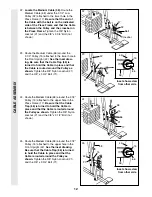
Page 12: ...n the 3 8 Nylon Locknut 21 and the 3 8 x 3 3 4 Bolt 71 24 Route the Medium Cable 58 around the 3 1 2 Pulley 15 attached to the upper hole in the Press Frame 17 Be sure that the Cable Trap 66 is turned...

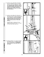
Page 13: ...t 2 and a 1 4 Flat Washer 10 Do not completely tighten the Nylon Locknut It should be threaded onto the end of the Cable only a couple of turns as shown in the inset drawing Attach the Small U Bracket...

Page 14: ...Locknut 3 31 Attach the Short Cable 35 to one of the three holes in the Leg Lever 29 with a 5 16 x 3 4 Bolt 89 a 5 16 Washer 8 and a 5 16 Nylon Locknut 3 Note The three holes are for cable adjustment...

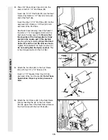
Page 15: ...the keyhole See the right inset drawing Orient the Short Cable 35 and the Curl Bar 86 as shown Tighten the indicated 5 16 Nylon Locknut 3 Do not overtighten the Nylon Locknut This is the storage posi...

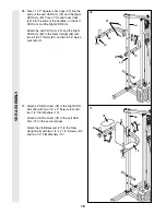
Page 16: ...m 80 to the Rear Upright 56 with two 5 16 x 3 Bolts 81 and two 5 16 Nylon Locknuts 3 37 Attach a VKR Armrest 78 to the Right VKR Arm 80 with two 1 4 x 2 Screws 24 and two 1 4 Flat Washers 10 Attach a...

Page 17: ...to be sure that the cables move smoothly over the pulleys If one of the cables does not move smoothly find and correct the problem IMPORTANT If the cables are not properly installed they may be damage...

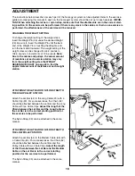
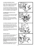
Page 18: ...en the Lat Bar and the Long Cable so the Lat Bar is in the correct starting position for the exercise to be performed The Nylon Strap 39 can be attached in the same manner ATTACHING THE LAT BAR OR NYL...

Page 19: ...a Cable Clip ATTACHING AND REMOVING THE CURL FRAME For some exercises the Curl Frame 84 must be attached to the Seat Frame 36 To attach the Curl Frame to the Seat Frame insert the pin on the Curl Fram...

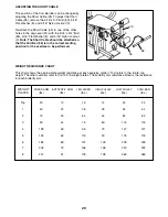
Page 20: ...t Washer 8 and 5 16 Nylon Locknut 3 Re attach the Short Cable 35 to one of the other holes in the Leg Lever 29 with the 5 16 x 3 4 Bolt 89 5 16 Flat Washer 8 and 5 16 Nylon Locknut 3 Note The Short Ca...

Page 21: ...le 23 see drawing 1 and at the end of the Short Cable 58 see drawing 2 To do this you may need to remove the Small U Bracket 67 from the Weight Tube 63 or remove the 3 1 2 Pulley 15 from the Long U Br...

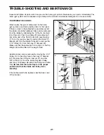
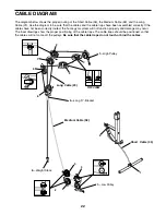
Page 22: ...been correctly routed the home gym system will not function properly and damage may occur The inset drawings show the proper positioning of the cable traps The cable traps should be positioned so tha...

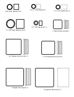
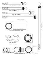
Page 23: ...32 5 1 3 4 Square Inner Cap 44 6 2 Square Inner Cap 27 2 2 Square Outer Cap 51 2 1 x 7 8 Plastic Bushing 75 2 1 Square Inner Cap 65 1 5 8 x 9 16 Spacer 73 1 1 2 x 3 4 Spacer 61 2 1 2 x 1 2 Bushing 87...

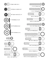
Page 24: ...2 Carriage Bolt 1 3 5 16 x 2 3 4 Carriage Bolt 14 3 1 4 x 1 2 Screw 18 6 5 16 x 2 1 2 Bolt 22 4 3 8 x 2 1 2 Bolt 7 3 1 4 x 2 Carriage Bolt 38 1 5 16 x 2 3 4 Bolt 1 1 6 5 16 x 2 1 4 Bolt 33 1 1 4 Nylo...

Page 25: ...e B1e e e 3 C5 J5e V4 0Y Ye W2 6Xe 7 eB1e e e 3X LeJ5e S e Ye UgW V K e O Y V4 0Y W KeO e e V Mg e W2 6Xe 7 eB1e e e 3 eC5e S He W2 Le 7 B B1e e e e e e e e g g W26T2 6Xe 7 B B1e e e 3 C C5e V40R4 0Y...

Page 26: ...Inner Cap 45 127180 2 10 Pad 46 127058 2 Press Arm 47 127059 1 Left Arm Key Part No No Qty Description 48 127060 1 Right Arm 49 120733 10 1 Round Inner Cap 50 126799 3 Long Cable Trap 51 105723 2 2 Sq...

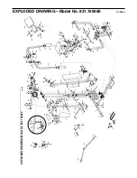
Page 27: ...5 3 21 66 15 20 74 49 46 31 46 22 3 9 16 15 21 58 59 17 21 44 44 66 73 71 49 13 40 38 37 18 32 28 30 34 10 2 24 36 30 34 14 33 3 29 34 30 28 30 34 15 12 2 57 58 21 10 66 56 75 31 78 80 81 81 10 24 77...

Page 28: ...ached to the frame See the front cover of this manual to find the location of the decal All replacement parts are available for immediate purchase or special order when you visit your nearest SEARS Se...

Reviews: