background image

Summary of Contents for 831.287620

Page 1: ...he locationshownbelow Write the serial number in the space above Serial Number Decal AUTION Read all safety precautions and instructions in this man ual carefully before using this equipment Save this manual for future reference PATENT PENDING OWNER S MANUAL SEARS ROEBUCK _ND CO HOFFMAN FRTATFR_ II RntTq ...

Page 2: ... small childrenaway from the CARDIO FIT at all times 4 The CARDIO FIT features a precision resistance cylinder due to the nature of resistance cylinders it is recommended that the floor underneath the CARDIO FiT be covered in case of slight oil leakage 5 The resistance cylinder becomes very hot during use Allow the resistance cylinder to cool before touching it When adjusting the resistance touch ...

Page 3: ...ttached to the CARDIO FIT see the front cover of this manual for the location of the i lecal iBe fore reading further please review the drawing below and familiarize yourself with the carts that are labeled ASSEMBLY Place all parts in a cleared area and remove the packing materials Do not dispose of the packing materials until assembly is completed Read each step carefully before beginning Use the...

Page 4: ...e ADJUSTING THE MAGNET AND REED SWITCH on page 8 If the Magnet is not aligned with the reed switch the monitor will not function 2 Make sure that there is a 1 2 Link Arm Bushing 19 in the left Link Arm 4 see the inset drawing Slide the left Unk Arm onto the indicated pin on the Pedal Frame 7 Pivot the Pedal Frame and tap a 1 2 Dome Cap 29 onto the pin _ttach the right Link Arm 4 in the same manner...

Page 5: ...he Pedal Frame 7 Apply a small amount of grease to the shaft Slide a Pedal 12 onto the shaft Using the included pedal tool tap a 1 2 Push Nut 30 onto the shaft Make sure that the Push Nut is turned so the teeth bend away from the Pedal see the inset drawing Attach the other Pedal not shown in the same manner 6 Remove the two 1 4 x 2 screws 17 attaching the Seat 3 to the underside of the Seat Tube ...

Page 6: ...n to the starting position raise your toes and rotate your heels down ward CAUTION To avoid injury keep you feet _ firmly on the pedals to prevent them from slipping UPPER BODY EXERCISE I To focus on the muscles of the upper body rest your feet on the foot pegs rather than the pedals as you _exercise Foot Peg ABDOMINAL EXERCISE To exercise your abdominal muscles keep your arms straight and bend ba...

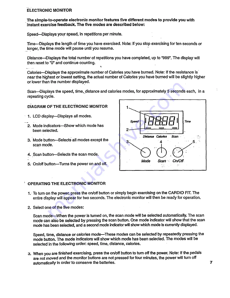
Page 7: ... Selects all modes except the scan mode 4 Scan button Selects the scan mode 5 On off buttonwTurns the power on and off Distance Ca on_s Scan _ Mode Scan On Off OPERATING THE ELECTRONIC MONITOR 1 To turn on the power press the on off button or simply begin exercising on the CARDIO FIT The entire display will appear for two seconds The electronic monitor will then be ready for operation 2 Select one...

Page 8: ...eattach the Monitor 11 to the Frame 6 Make sure that the wire on the Monitor is plugged into the sensor wire Insert any excess wire into the Frame Make sure not to pinch the wire between the Frame and the Monitor ADJUSTING THE MAGNET AND REED SWITCH If the monitor does not function properly the Magnet 27 and Reed Switch 15 should be checked Pivot the Pedal Frame 7 until the Magnet is aligned with ...

Page 9: ...ow end of your trainingzone as you exercise After a few months your heart rate can be increased gradually until it is near the middle of your training zone as you exercise To measure your heart rate stop exemising and place two fingers on your wrist Take a six second heartbeat count and multiply the result by 10 to find your heart rate For example if your six second heartbeat count is 14 your head...

Page 10: ...7530 2 1 1 4 x2 Endcap 31 118213 14 117553 1 Bumper 32 117448 15 101743 1 Reed Switch Sensor Wire 33 118904 16 013162 6 8 xl 2 Screw 117744 17 013498 2 l 4 x2 Screw 118061 18 013492 2 1 4 x 5 8 Screw _ 4 1i 2 LinkArm Bushing 4 3 8 Spacer 1 1 2 x 11 1 4 Pivot Rod 1 1 2 x 3 1 2 Rod 2 1 2 Cylinder Bushing Set 2 15 16 Spacer 6 1 2 Pivot Bushing 2 5 16 Washer 1 Magnet Retainer 1 1 2 x 5 1 2 Rod 8 1 2 D...

Page 11: ...EXPLODED DRAWINGmModel No 831 287620 R594B 11 3 I 1 I 8 33 33 11 ...

Page 12: ...ucts having the parts tools and equipment to ensure that we meet our pledge to you We service what we sell Should you ever need repair service or parts call toll free For repair service 1 800 4 REPAIR 1 800 473 7247 FOr repair parts 1 80O FON PART 1 800 366 7278 FULL 90 DAY WARRANTY For 90 days from the date of purchase when proper assembly and maintenance procedures detailed in the Owner s Manual...

Reviews: