6
STEP 2
: (Unloading and Unpacking)
1. After unloading the lift, place it near the intended installation location.
2. Remove the shipping bands and packing materials from the unit.
3. Remove the packing brackets and bolts holding the two columns together. (Do not discard bolts, they
may be used in the assembling of the lift
)
4. Take out the up-rights, lifting arms, pads, accessory box, oil pipes, etc, from the column. Check the
quantity of every item with the pats list. If any missing, please contact with your dealer at once.
STEP 3
: (Site Layout)
1. Determine which side will be the approach side.
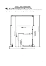
2. Now determine which side you prefer the power unit to be located on.
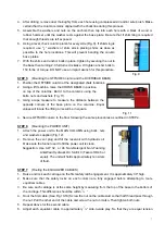
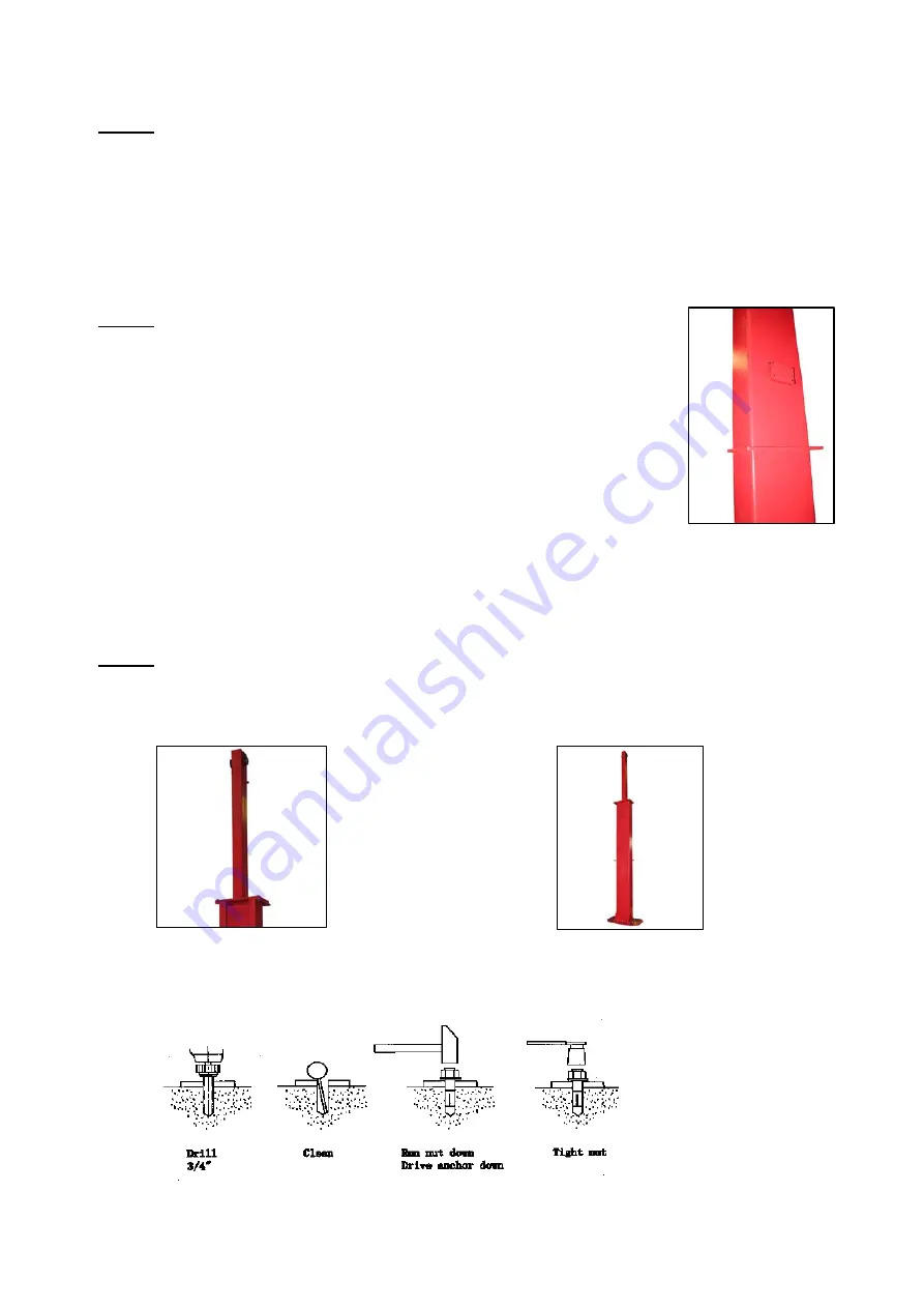
The main column has the power-unit mounting bracket attached to the
side (Fig. 5). Note the main column can be located on either side. It is
helpful to try and locate the power side with the driver side of the vehicle
when loaded on the lift to save steps during operation.
3. Once a location is determined, use a carpenter’s chalk line to layout a
grid for the post locations.
Fig. 5
4. After the post locations are marked, use a chalk or crayon to make an outline of the posts on the floor
at each location using the post base plates as a template.
5. Double check all dimensions and make sure that the layout is perfectly square.
STEP 4
: (Installing the Main Column)
1. Before proceeding, double check measurements and make certain that the bases of each column are
square and aligned with the chalk line.
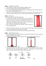
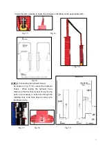
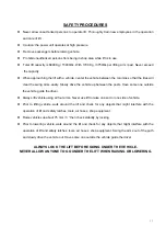
2. Assemble the uprights to the columns. Raise the columns to a vertical position (See Fig.6 & 7)
Fig. 6 Fig. 7
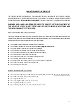
3. Using the base plate on the main column as a guide, drill each anchor hole in the concrete
approximately 5
1
/
2
” deep using a rotary hammer drill and
3
/
4
” concrete drill-bit. To assure full holding
power, do not ream the hole or allow the drill to wobble. (See Fig.8)
Fig. 8
Summary of Contents for 165915LK
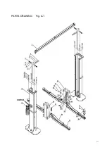
Page 16: ...PARTS DRAWING Fig A 1...
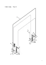
Page 17: ...Cable routing Fig A 2...


