background image


4.  After drilling, remove dust thoroughly from each hole using compressed air and/or wire brush. Make 

certain that the column remains aligned with the chalk line during this process. 

5.  Assemble the washers and nuts on the anchors then tap into each hole with a block of wood or 

rubber hammer until the washer rests against the base plate. Be sure that if shimming is required 

that enough threads are left exposed. 

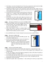
6.  Using a level, check column plumb for every side (Fig. 9). If shimming is 

required, use 

3

/

“ washers or shim stock, placing shims as close as 

possible to the hole locations. This will prevent bending the column 

base plates. 

7.  With the shims and anchor bolts in place, tighten by securing the nut to 

the base then turning 2-3 full turns clockwise. Or tighten anchor bolts to 

150 ft-lbs. of torque. DO NOT use an impact wrench for this procedure. 

Fig. 9 

STEP 5

:    (Mounting the OFFSIDE Column and the OVERHEAD BEAM) 

1.  Position the OFFSIDE column at the designated chalk locations. 

2.  Using a lift machine, raise the CROSS BEAM in position 

on top of the columns. Bolt it to the columns using the 

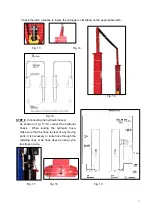
bolts, nuts and washers (Fig. 11).                                                 

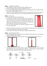
3.  Using a tape measure to measure the distance between the 

opposite corners of the base plate on the columns. Equal 

values will insure the lifting arms will be in square.   

Fig. 11 

4.  Secure OFFSIDE column to the floor following the same procedures as outlined in STEP 4. 

 
STEP 6

:    (Mounting the POWER UNIT) 

1.  Attach the power unit to the MAIN COLUMN using bolts, nuts 

and washers supplied (Fig. 12). 

2.  Remove the vent plug and fill the reservoir with hydraulic oil. 

Make sure the funnel used to fill the power unit is clean. 

Suggestion: Use AW 32, or 46 Non-Detergent Non-Foaming 

Anti-Wear Hydraulic Oil. SAE-10 (Texaco HD46 or 

equal). The unit will holds approximately ten Liters 

of fluid. 

                                                                                                                                                  Fig. 12 

STEP 7

:    (Routing the EQUALIZER CABLES) 

1.  Raise and lock each carriage on the first safety latch engagement. It is approximately 30” high. 

2.  Make sure that the safety locks on each column are fully engaged before attempting to route 

equalizer cables. 

3.  Be sure each carriage is at the same height by measuring from the top of the base to the bottom of 

the carriage. This difference should be within 

1

/

.  

4.  Rout the first cable. (See Fig 13-16) Screw the nut on the cable stud so that half thread pass through 

the nut. Pull the other end of the cable and screw the nut on it also. Then tighten both nuts.   

5.  Repeat above for the second cable. 

6.  Adjust each equalizer cable to approximately 

1

/

” side-to-side play. So that they are equal tension. 

Summary of Contents for 165915LK

Page 1: ...Model 165915LK Clear Floor Two Post Lift 6800 Kg 15000lbs Capacity ASSEMBLY OPERATION INSTRUCTION May 2015...

Page 2: ...cement The lift is intended to raise the entire body of the vehicle Do not attempt to lift only part of the vehicle Improper use of this equipment could result in damage to the lift yourself or other...

Page 3: ...ll with 3 4 Masonry Drill Bit Core Drill ReBar Cutter recommended Hammer and Hex Key Allen Wrench Set Sockets and Open Wrench set 1 2 thru 1 1 2 1 1 8 for 3 4 Anchors Medium Crescent Wrench and Medium...

Page 4: ...ecting Site Before installing your new lift check the following 1 LIFT LOCATION Always use architects plans when available Check layout dimension against floor plan requirements making sure that adequ...

Page 5: ...as heaters building supports electrical lines etc 3 DEFECTIVE CONCRETE Visually inspect the site where the lifts will be installed and check for cracked or defective concrete 4 FLOOR REQUIREMNETS The...

Page 6: ...ocate the power side with the driver side of the vehicle when loaded on the lift to save steps during operation 3 Once a location is determined use a carpenter s chalk line to layout a grid for the po...

Page 7: ...ce between the opposite corners of the base plate on the columns Equal values will insure the lifting arms will be in square Fig 11 4 Secure OFFSIDE column to the floor following the same procedures a...

Page 8: ...Fig 15 STEP 8 Connecting the hydraulic hoses As shown on Fig 17 19 connect the hydraulic hoses When routing the hydraulic hose make sure that the hose is clear of any moving parts It is necessary to...

Page 9: ...TEP 11 Ceiling limit device To install this ceiling limit device first is to use the rope grip fix one end of the steel rope on the washer on the offside column Fig 21 Line the rope through another wa...

Page 10: ...p into each latch stop But to lock the lift you must press the Lower level to relieve the hydraulic pressure and let the latch set tight in a safety position Always lock the lift before going under th...

Page 11: ...Have some one outside the vehicle guide the driver z Always lift vehicle using all four arms Never use lift to raise one end or one side of vehicle z Prior to lifting vehicle walk around the lift and...

Page 12: ...al injury and even death z Check safety lock audibly and visually while in operation z Check safety latches for free movement and full engagement with rack z Check hydraulic connections and hoses for...

Page 13: ...s z Replace cables and sheaves z Replace or rebuild air and hydraulic cylinders as required z Replace or rebuild pumps motors as required z Check hydraulic and air cylinder rod and rod end threads for...

Page 14: ...will not run A Lift overloaded remove excessive weight from lift B Bad capacitor call electrician C Low voltage call electrician D Faulty wiring call electrician 5 Lift jerks going up and down A Air i...

Page 15: ...1 1982 before beginning any lift repairs Shall not modify the lift in any manner without prior written consent of the manufacture Shall display the operating instructions and Lifting It Right and Safe...

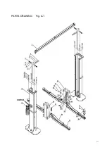
Page 16: ...PARTS DRAWING Fig A 1...

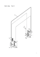
Page 17: ...Cable routing Fig A 2...

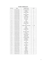
Page 18: ...15 165915 01 015 Bolt 4 16 165915 01 016 Bushing 4 17 165915 01 017 Spring Washer 4 18 165915 01 018 Nut 4 19 165915 01 019 Hydraulic Pump 1 20 165915 01 020 Carriage 2 21 165915 01 021 Safety Jointin...

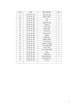
Page 19: ...5 01 046 Steel Cable 2 47 165915 01 047 Self lock Nut 4 48 165915 01 048 Spindle 2 49 165915 01 049 Idler Wheel 2 50 165915 01 050 Multiple Bush 2 51 165915 01 051 Self lock Nut 4 52 165915 01 052 hyd...

Page 20: ...Fig A 8 DURO MOTOR PUMP DRAWING...

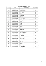
Page 21: ...165915 02 009 Circlip 1 10 165915 02 010 Joint 1 11 165915 02 011 Circlip 1 12 165915 02 012 O ring 1 13 165915 02 013 O ring 1 14 165915 02 014 Gear pump 1 15 165915 02 015 Suck pipe assembly 1 16 1...

Page 22: ...release valve 1 32 165915 02 031 Ball 1 33 165915 02 032 Hex socket threaded pin 1 34 165915 02 033 Ball seat 1 35 165915 02 034 Spring 1 36 165915 02 035 Threaded pin 1 37 165915 02 036 O ring 1 38 1...

Reviews: