11
3. Unpack the lift. Remove the swing arms, bolt box, power unit box, and overhead beam.
A. Save all packing hardware, as these components are necessary to complete the
installation.
B.
Remove the bolts
from the uprights which hold the two columns together.
C.
Remove the upper column.
Do not
stand the columns up now but lay the columns with
their flat backs on the floor.
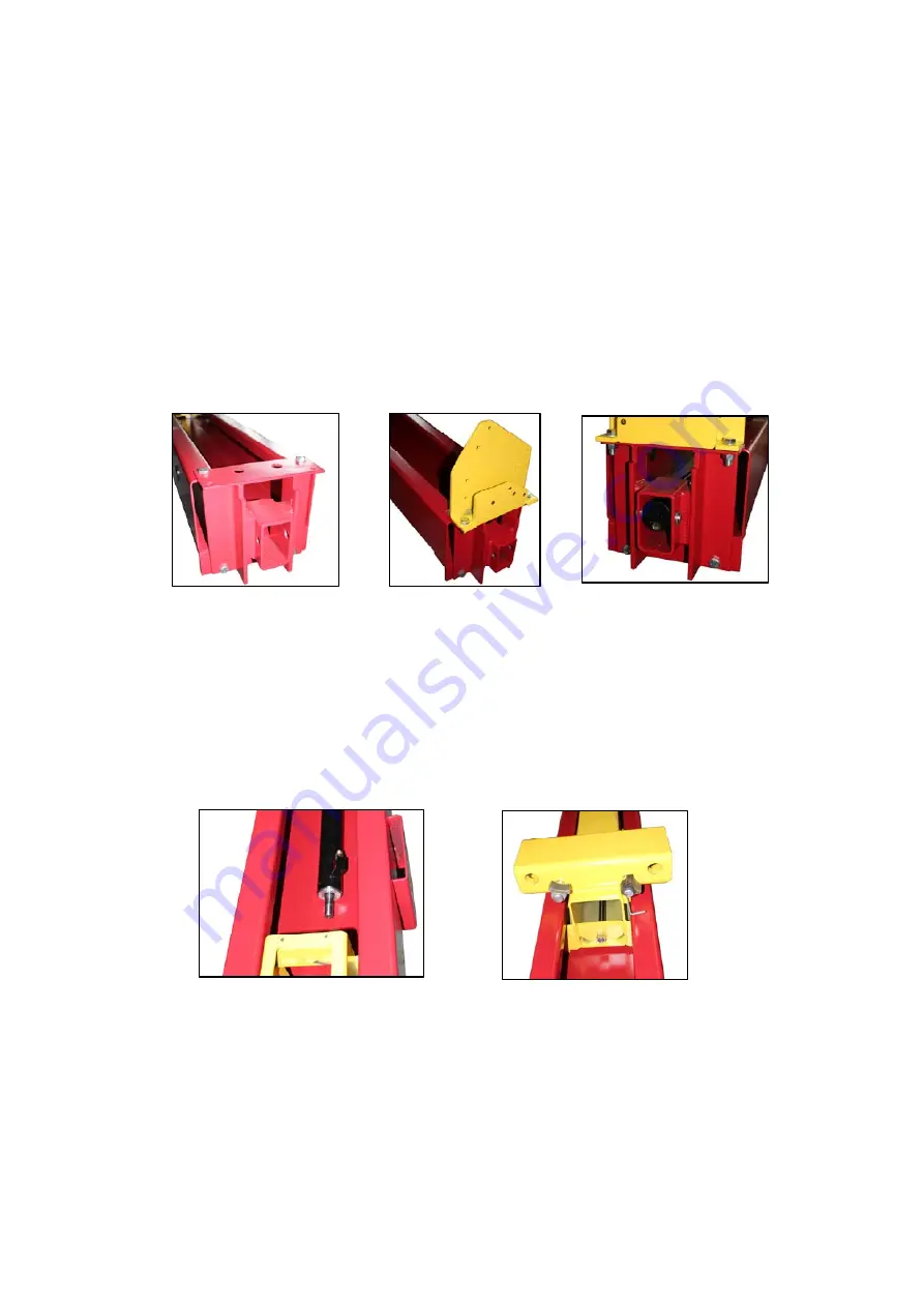
4. Attach the cylinder base and the cross beam base on the column using bolts, washers
and nuts provided as shown in figure 4a &4b.
Fig. 4a Fig. 4b Fig. 5a
5. Install
hydraulic
cylinders.
A. Install the cylinder to the cylinder base with
cylinder pin and the bolts, bushings
(spacers), washers, and nylon nuts, as in figure 5.
B. The hose connecting port near the other end of the cylinder should be positioned
pointing to the column’s opening. (Fig. 5b)
C. Bolt the cylinder rod with the carriage.
(
Fig. 5c
)
Fig. 5b Fig. 5c
Summary of Contents for 165948BLK
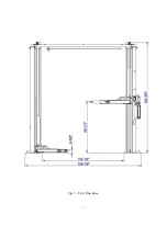
Page 7: ...7 Fig 1 Front View Spec...
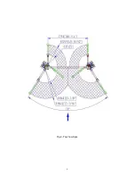
Page 8: ...8 Fig 2 Top View Spec...


