background image

12 


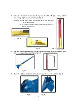
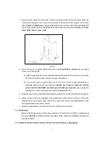
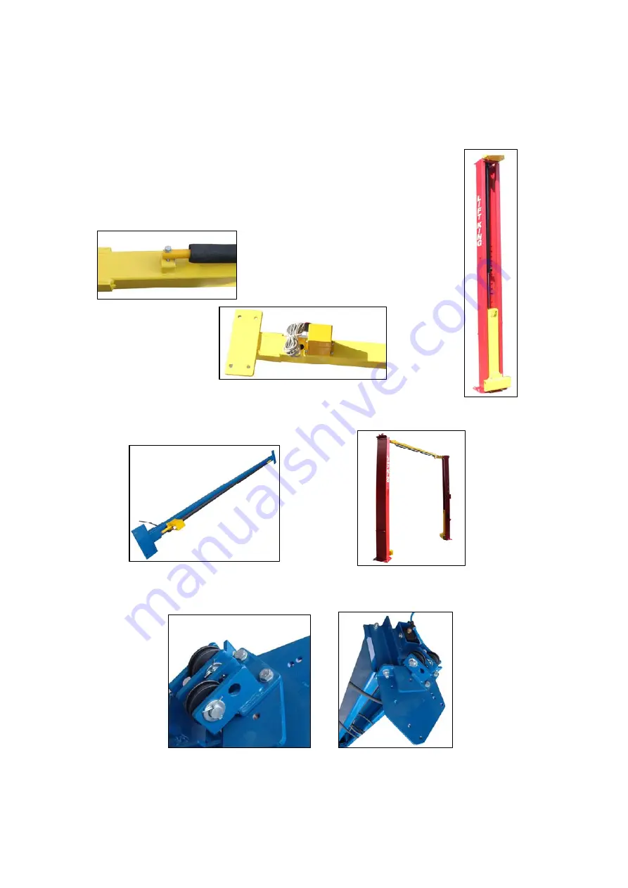
6.  Set up the columns at e desired place facing each other. Then lift up the carriage to first 

latch locking height (about one foot high). (Fig. 6) 

Attention: (1) the main column is suggested at the left hand with 

vehicle head forward. 

         (2) the distance between column to wall is suggested to be 

at least 2 feet for safe.   


Fig. 7a


                                                        Fig. 7b                                        Fig. 6 

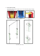
7.  Assemble the ceiling safety device to the overhead cross beam. (Fig. 7a, 7b & 7c) Then 

Install the beam on the column tops. (Fig. 7d ) 


Fig. 7c                                                                      Fig. 7d 

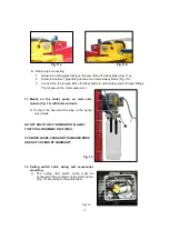
8.  Mount the cable seat with roller on the beam base at the top of the column. (Fig. 8)   


Fig.8a                                  Fig. 8b 

Summary of Contents for 165948BLK

Page 1: ...Model 165948BLK Turned Two post Hydraulic Lift Clear Floor type Operation Manual 2nd edition Manufactured exclusively for Liftking Hoists May 2015...

Page 2: ...anual 2 1Product Description 2 2Technical Data 3 Installation 3 1Site Selection 3 2Surface Condition 3 3Tools Required 3 4Installation Procedure 3 5Hydraulic Scheme 3 6Control Box Diagram 4 Operation...

Page 3: ...d and understood the warning instructions 1 2 Important Information 1 Read this manual thoroughly before installing operating or maintaining this lift 2 This lift is designed for indoor use only and s...

Page 4: ...have properly engaged the vehicle before raising the lift to a working height 7 Keep everyone clear of the lift when the lift is moving the locking mechanism is disengaged or the vehicle is in danger...

Page 5: ...hese restricted procedures include but are not limited to the following cylinder replacement carriage and safety latch replacement column replacement overhead structure replacement 20 Anyone who will...

Page 6: ...sts of a fixed structural unit base and posts the mobile unit carriage and arms the hydraulic power system and safety devices 2 2 Technical Data Capacity 4 500 kg 10000lbs Lifting Height 1 630mm 64 3...

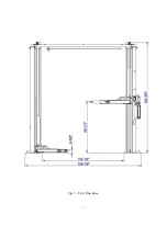
Page 7: ...7 Fig 1 Front View Spec...

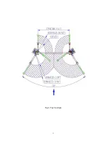
Page 8: ...8 Fig 2 Top View Spec...

Page 9: ...kness concrete with a minimum compressive strength of 3 000 psi reinforced with steel bar Failure in accomplish the foundation requirement may cause the lift instability or personal injury Installing...

Page 10: ...ne if the site is adequate for the lift model being installed see figures 1 2 for typical bay layout and ceiling height requirements B Snap chalk lines to identify the lift s centerline Fig 3 Fig 3 Sn...

Page 11: ...th their flat backs on the floor 4 Attach the cylinder base and the cross beam base on the column using bolts washers and nuts provided as shown in figure 4a 4b Fig 4a Fig 4b Fig 5a 5 Install hydrauli...

Page 12: ...d at the left hand with vehicle head forward 2 the distance between column to wall is suggested to be at least 2 feet for safe Fig 7a Fig 7b Fig 6 7 Assemble the ceiling safety device to the overhead...

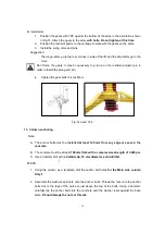
Page 13: ...13 9 Rout the balancing cables Rout the balancing steel cables according to Fig 9a 9b 9c 9d 9e from carriage to carriage through the cable rollers Fig 9a Fig 9b Fig 9c Fig 9d 9e cable routing...

Page 14: ...cylinder in off side column to the top of main side column Remember to rout the hose through the hook on cross beam Fig 10a 10b 2 Then through a T fitting one middle length hose connecting to the main...

Page 15: ...n it goes to the motor pump also 11 Mount on the motor pump on main side column Fig 12 with bolts and nuts A Connect the hose and the pipe to the pump valve block DO NOT HOLD THE CYLINDER ROD IN A WAY...

Page 16: ...4 Tighten the gear bolts to 40 46N m Fig 14a and 14 b 13 Column anchoring Note A The anchor bolts must be installed at least 145 mm from any edge or seam in the concrete B The concrete must be at lea...

Page 17: ...dment or adequate spacing cannot be achieved replace the concrete under the column with a 1220 X 1220 X200 mm thick pad of 3 000 psi concrete keyed under the existing floor Let the concrete cure befor...

Page 18: ...ft empty to the top of its travel and lower it to the floor three 3 times to remove the remaining air from the hydraulic system B The latches should click together as the lift is being raised C The fi...

Page 19: ...Oil Tank 2 Mesh 3 Gear Pump 4 Power Unit 5 Overflow Valve 6 One way Valve 7 Cylinder 8 Hand Release Valve 9 Pressure Gauge not supplied Hydraulic Pump 2 2KW 2850 rpm Setting Pressure 20 Mpa Flow rate...

Page 20: ...re to read and familiarize yourself with the Safety Instructions at the beginning of this manual Failure to follow Safety Instructions may result in property damage personal injury or death 4 1 Cautio...

Page 21: ...er s recommended lift points Use intermediate high step or optional adapters for under body clearance when required Typical Lifting Points Some Vehicle may have the manufacturer s Service Garage Lift...

Page 22: ...nded lift point z Vehicle is stable on lift z The overhead switch bar will contact the highest point on the vehicle 4 2 4 While Using Lift a Avoid excessive rocking of vehicle while on lift b Always u...

Page 23: ...icate the four inside corners of the columns with heavy duty bearing grease 9 With lift lowered check the hydraulic fluid level If necessary add oil as described in the Installation Instruction sectio...

Page 24: ...24 Adaptor Figure 16 can connect with pressure gauge for diagnosing leaking problem Pressure Gauge can connect to the hydraulic circuit via the adaptor the arrow below Figure 16...

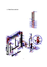
Page 25: ...0 59 58 30 29 31 32 51 52 54 37 38 39 40 41 42 15 43 45 44 46 47 48 49 50 36 34 89 90 34 91 92 12 24 4 5 6 19 6 8 10 9 11 7 88 6 7 13 14 35 15 16 15 14 A 79 22 20 21 84 85 30 A 83 93 76 77 78 55 53 34...

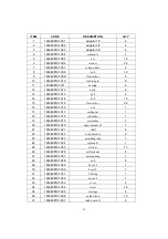
Page 26: ...6 165948B 01 016 nut 1 17 165948B 01 017 ceiling bar 1 18 165948B 01 018 soft rubber 1 19 165948B 01 019 crossbeam 1 20 165948B 01 020 angle bracket 2 1 21 165948B 01 021 shaft 4 22 165948B 01 022 dol...

Page 27: ...2 165948B 01 052 O ring 1 53 165948B 01 053 fitting 1 54 165948B 01 054 anchor 12 55 165948B 01 055 shim 16 56 165948B 01 056 Circlip 2 57 165948B 01 057 cover 2 58 165948B 01 058 arm extension 1 2 59...

Page 28: ...ng 1 75 12 165948B 03 075 12 nut 1 75 13 165948B 03 075 13 cylinder body 1 75 14 165948B 03 075 14 fitting 2 76 165948B 01 076 cable 2 77 165948B 01 077 washer 4 78 165948B 01 078 nut 8 79 165948B 01...

Page 29: ...nce the vehicle weight on lift D Problem Lift slowly settles down Possible cause Solution 1 Debris in check valve seat 2 Debris in lowering valve seat 3 External oil leaks 1 Clean check valve 2 Clean...

Reviews: