16
B. Install arms
1.
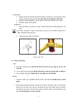
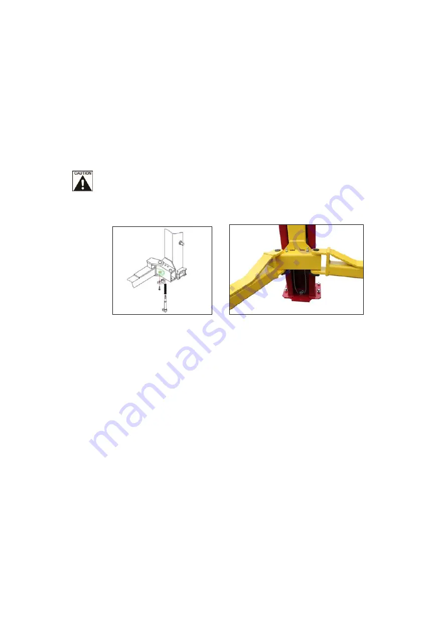
Position the gears with TOP against the bottom of the arms in the orientation shown
in Fig.14. Attach the gears to the arms
with bolts.
Do not tighten at this time.
2.
Position the restraint pawls on the carriage to mate with the gears on the arms.
3.
Install the swing arms and pins.
Suggestion:
The longer arms go to the rear or drive in side of the lift, and the short arms go to the
front.
Don’t force the gears, it may be necessary to pull up on the restraint actuator pin in
order to install the swing arm pin.
4. Tighten the gear bolts to 40~46N-m.
Fig. 14a and 14 b
13. Column anchoring.
Note:
A. The anchor bolts must be
installed at least 145 mm from any edge or seam in the
concrete.
B. The concrete must be at least
108 mm thick with a compressive strength of 3,000 psi.
C. Use a hammer drill with
a Carbide tip, 19 mm diameter, solid drill bit.
↓
STEPS:
1. Using the column as a template, drill the anchor bolt holes
for the Main side column
Only!!
2. Assemble the washers and nuts onto the anchor bolts. Thread the nuts onto the anchor
bolts where the tops of the nuts are just above the top of the bolts. Using a hammer,
carefully tap the anchor bolts into the concrete until the washer rests against the base
plate.
Do not damage the nuts or threads.
Summary of Contents for 165948BLK
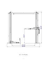
Page 7: ...7 Fig 1 Front View Spec...
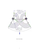
Page 8: ...8 Fig 2 Top View Spec...

