background image


165982HLK 

Dec. 2020 

Safety Cautions 

1.1 Important statements 


Please do note the tonnage mark on the machine. Do not try to lift any load that exceeds the rated 
lifting capacity.     

Please read this manual carefully before installation and use of the lift, to avoid any property loss 
or personal injury caused by faulty operation.     

No one is allowed to modify the control part and other mechanical parts of the machine without 
the manufacturer’s permission.       

1.2  Instructions for qualification of operators and users   

1.2.1    Only personnel who have received professional training are allowed to operate and use 

the lift.     

1.2.2    Electrical connection must be performed by qualified electricians.       

1.2.3    Nonprofessionals shall not approach the lifting area.       

1.3 Cautions  

1.3.1    Do not install the lift on asphalt or tar ground. Concrete thickness must meet requirement.     

1.3.2    Please read and understand Safety Cautions carefully before operation of the lift.       

1.3.3    The lift shall not be used outdoor if not being customized to special requirements.     

1.3.4    Hands and feet shall be away from moving parts of the lift. Move hands and feet away 

when the machine is descending, to avoid being crushed.   

1.3.5    Only personnel who have received professional training are allowed to operate and use 

the lift.     

1.3.6    Operators are not allowed to wear fat and loose clothes, to avoid being clamped by any 

moving part when the machine is descending or rising.     

1.3.7    Ground around the lift must be kept clean and tidy, with no stacking of materials, in order 

to avoid accident.         

1.3.8    The lift is designed to lift the entire car, not part of it. Do not try to lift any car beyond the 

rated lifting capacity.   

1.3.9    Do make sure the safety lock of the lift is locked when personnel are working undercar.     

1.3.10  Lifting block of the lift must be put at a place suggested by the car manufacturer, and then 

the car shall be lifted slowly. Check the car is stable without any risk of tipping, overturn or 
falling, before lifting it to the desired height.     

1.3.11  Check whether any part is broken and check synchronicity of the machine and flexibility of 

moving parts at any time. Perform regular maintenance. Once any anomaly is detected, 
stop use immediately and contact your dealer.         

1.3.12    Please lower the machine to the lowest position and turn off power after operation.   

1.3.13    It is not allowed to modify any part of the lift without the manufacturer’s permission.     

Summary of Contents for 165982HLK

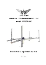
Page 1: ...Dec 2020 MOBILE 4 COLUMN PARKING LIFT Model 165982HLK Installation Operation Manual...

Page 2: ...Instructions 10 3 1 Preparation before installation 3 2 Cautions for installation 3 3 Installation procedures 3 4 Last check 4 Operation Instructions 15 4 1 Cautions for operation 4 2 Operation flow...

Page 3: ...s and feet away when the machine is descending to avoid being crushed 1 3 5 Only personnel who have received professional training are allowed to operate and use the lift 1 3 6 Operators are not allow...

Page 4: ...drain liquid at random in order to protect environment 1 4 Safety signs 1 5 Noise standard The lift makes noises less than75dB For your health it is suggested to provide a noise meter in your operatin...

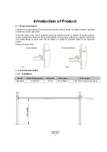
Page 5: ...oil pushes cylinder rod up pulling steel cable and hence raising tracks During lifting safety rack engages with safety lock automatically to make sure that no falling is caused by possible faults of...

Page 6: ...165982HLK Dec 2020 6 Fig 4 Fig 5...

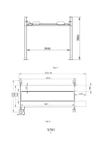
Page 7: ...165982HLK Dec 2020 7 2 3 Main structure chart 1 Control case mounting bar 3 Power unit Motor pump 4 Main platform 5 Wheel rack 6 Offside platform 7 Column and cap 8 Cross beam 9 Approach ramp Fig 9...

Page 8: ...being above 3000psi and the thickness being 200mm or greater Within whole area the flatness error being less than 5mm Newly poured concrete shall be cured for more than 20 days in dry condition witho...

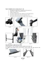
Page 9: ...165982HLK Dec 2020 9 Fig 10 Step 3 Unloading and unpacking Step 4 Set up of columns Fig 11 After unpacking set up the four columns as Fig 11 Fig 11 Main column with holes on base plate...

Page 10: ...let the crossbeam rest on 4th position Fig 15 5 Put in the nylon sliders and mount on the cover plate Fig 16 17 The slider with cut must be at the column cutting corner as in the picture Fig 12 Fig 13...

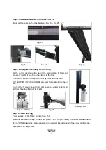
Page 11: ...as Fig 18 The one for main column is with holes Fig 21 2 Pull the cylinder to make sure that the cables are long enough 3 Put on the cable cut safe roller on the latch Fig 22a 4 Get the cables out fro...

Page 12: ...motor pump on the bar by bolts and nuts also Fill 10L 9PRO 12L 9XL HM46 anti wear hydraulic oil into the oil tank Connect the hydraulic hose from motor pump to cylinder under main platform through a f...

Page 13: ...sition It will be stopped by the cylinder extension limit While rising the locks will knock the columns making Clang Clang noise It is normal that the sound may not synchronous It depends on the level...

Page 14: ...wed where safety device is faulty 4 1 3 Check whether the center of gravity of the car to be lifted is at the center of the lifting platform If not please adjust the center of gravity before lifting 4...

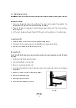
Page 15: ...Lowering the lift 1 Press UP button 2 3 seconds to rise the platforms a little height 2 Hold down the lock release lever and the DOWN lever to lower the platforms 2 Drive the car off after the lift d...

Page 16: ...en oil suction pipe Buffer valve is loose or blocked Tighten or clean buffer valve Slow lowering down occurs after lifting Check if there is oil leakage at any conduit Replace conduit Cylinder is seal...

Page 17: ...lowering brackets 6 2 Items to be checked weekly Check flexibility of moving parts Check conditions of safety parts Check volume of hydraulic oil by pressing the lifting button to raise the platform...

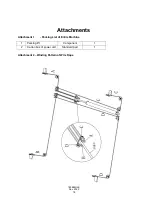
Page 18: ...65982HLK Dec 2020 18 Attachments Attachment 1 Packing List of Entire Machine 1 Parking lift Component 1 2 Carton box of power unit Standard part 1 Attachment 2 Winding Pattern of Wire Rope Cylinder ro...

Page 19: ...165982HLK Dec 2020 19 Attachment 3 Hydraulic Schematic Diagram...

Page 20: ...165982HLK Dec 2020 20 Attachment 4 Exploded View of Machine Parts Drawing Fig 2 Parts Drawing Fig 3...

Page 21: ...165982HLK Dec 2020 21 Parts Drawing Fig 4 Parts Drawing Fig 5...

Page 22: ...165982HLK Dec 2020 22 Parts Drawing Fig 6 Parts Drawing Fig 7...

Page 23: ...165982HLK Dec 2020 23 Parts Drawing Fig 8 Parts Drawing Fig 9...

Reviews: