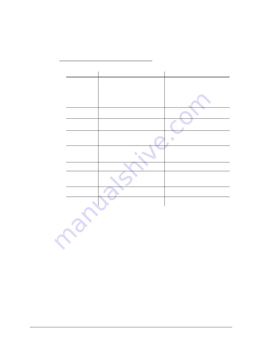
background image

No display

SITUATION

CAUSE

ACTION

5.1  

   TROUBLE SHOOTING

1) No power input

2) Power connection error

3) Display damaged

4) Display board IC error

or  power input 

    connection error

or two board connection 

    error

5) Contrast decay

1) Check power supply
2) Check power connection 
3) Replace  display
4) Check the IC and all the connections
5) Adjust the LCD contrast

1) Display IC reverse install
2) Display IC  damaged

1) Check Display IC installation and quality

LED MODULE 
on, but no control 
from display

Display normal, 
but no response 
from buttons

1) Buttons damaged
2) Display IC damaged

1 ) R e p l a c e  b u t t o n s
2) Replace Display IC

1) Signal Cable error
2) Signal conncetion error
3) The DMX signal receive IC damaged
4)  DMX address error

No DMX signal 

1) Check all signal Cables
2) Check all signal  conncetions
3) Check the DMX signal receive IC
4) Check DMX address

1) The heat sensor resistance of LED board 
      error
2) The temperature protection circuit on the 
      display error.

When the surface  
temperature of the 
unit exceed 75

, the 

temperature protection  
no work .

1) Replace the heat sensor resistance.
2) Check the temperature protection circuit.

1) Check LEDs joining
2) Check lens installing

1) LED not joining well
2) Lens not installing well

Color mixing 
uneven,with splash

1) LED damaged
2) LED damaged or Main PCB 

LEDs of the same
 color are not lit

1) Replace LEDs
2) Replace damaged LED or Main PCB

1) Replace saving IC

1) Saving IC damaged

Manual and program 
can not save

20

5


APPENDIX

1) Check driver current of the partial color 
     LEDs on the Driver PCB
2) Check LED quality 
3) Reset to factory default setting.

1) The current of one of the color group LEDs 
is too strong or too weak. 
2) LED brightness not enough

Partial color

partial red,partial 

green, partial blue
 or partial white

Summary of Contents for LEDPAR 54

Page 1: ...USER MANUAL Please Read Over This Manual Before Operating The Light Fixture ...

Page 2: ... 9 EDITING CUSTOM PROGRAMS 12 3 12 WHITES BALANCE 13 PART 1 PRODUCT GENERAL 1 1 1 PRODUCT INTRODUCTION 1 1 2 PRODUCT FEATURES 1 1 3 TECHNICAL SPECIFICATIONS 2 1 4 PHOTOMETRIC DATA 3 1 5 SAFETY WARNING 4 PART 2 INSTALLATION 5 2 1 MOUNTING 5 2 3 SETTING UP WITH A DMX512 CONTROLLER 6 2 3 1 DMX512 ADDRESSING WITHOUT ID ADDRESSING 6 2 3 2 DMX512 ADDRESSING WITH ID ADDRESS 6 2 2 POWER CONNECTION 5 3 3 E...

Page 3: ...s to be controlled from any DMX512 controller This product can be operated as a single unit or in multiple units for large applications 1 2 PRODUCT FEATURES LED FIXTURE 1 DIM1 4 RGBW Dimmer 0 100 Strobe Built in automatic programs Upload custom parameters to slave fixtures LED display Display control lock out Direct DMX512 input Independent ID address Different white colors setting Over heat prote...

Page 4: ... 14 x GREEN 14 x BLUE 12 x WHITE Weight LED Unit Output LED Cooling 3W 270 x 270 x 490mm 3 2Kg 100 250V 50 60Hz 200W 2 Environment Temperature 20 40 öÓÃÓÚÆÀ À æÈ ËùÓÐ c by Foxit Software Company 2004 ÓÉ Foxit PDF Editor à fan öÓÃÓÚÆÀ À æÈ ËùÓÐ c by Foxit Software Company 2004 ÓÉ Foxit PDF Editor à ...

Page 5: ...LUX 15 BLUE 1 2 3 0 1 2 3 1360 256 120 68 46 LUX 15 WHITE 1 2 3 0 1 2 3 2 4 6 8 10Distance m 4613 1204 552 326 230 LUX 15 RGB 1 2 3 0 1 2 3 2 4 6 8 10Distance m 11340 2885 1285 765 530 LUX 15 1 2 3 0 1 2 3 2 4 6 8 10Distance m 16300 4000 1900 1122 752 LUX 15 RGB WHITE 2 4 6 8 10Distance m 2 4 6 8 10Distance m 2 4 6 8 10Distance m ...

Page 6: ...roducts The earth wire must always be connected to the ground Do not touch the power cables if your hands are wet ATTENTION This product left the place of manufacture in perfect condition In order to maintain this condition and for safe operation the user must always follow the instructions and safety warnings described in this user manual Avoid shaking or strong impacts to any part of the equipme...

Page 7: ... may be connected in series The LED MODULE can be mounted at any angle and in any position It is possible to further adjust the angle of the LED MODULE using the two adjustment knobs located on the side of the fixture 2 2 POWER CONNECTIONS 5 Note 1 As this fixture s DMX signal cable connection is Parallel connection so if over 32 units to be connected then a DMX signal amplifier is needed 2 If the...

Page 8: ...Settings menu on the fixture Each DMX Address may be used as many times as required Any DMX address in the range from 001 to 512 may be used Connect the DMX512 controller to the units in series 2 3 2 DMX512 ADDRESSING WITH ID ADDRESS STAG MODE Connect the DMX512 controller to the units in series Each unit has 11 DMX channels so the DMX Addresses should increase by increments of 11 e g 1 12 23 34 E...

Page 9: ...h allows the user to collectively control the whole group of units at that DMX address by setting CH11 to 0 or to control each unit independently by first selecting the DMX address and then by using CH11 to locate the target ID address 7 DMX Addr 1 ID Addr 1 DMX Addr 1 ID Addr 2 DMX Addr 1 ID Addr 3 DMX Addr 12 ID Addr 1 DMX Addr 12 ID Addr 2 DMX Addr 12 ID Addr 3 ...

Page 10: ...u or confirm the current function value scroll UP through the menu list or increase the value of the current function scroll DOWN through the menu list or decrease the value of the current function scroll through the main menu or return to the main menu MENU 3 DISPLAY PANEL OPERATION 8 ENTER UP DOWN MENU ENTER ...

Page 11: ...0 255 0 255 0 255 0 20 0 255 0 255 SET UPLD ID POW ON OFF NORM HIGH KEY ON OFF STAG Arc 1 Arc 2 Ar1 d Ar2 s Ar2 d WT01 WT02 WT11 Red Green Blue White 0 255 0 255 0 255 0 255 MENU Red Green Blue White 0 255 0 255 0 255 0 255 Strob 0 20 STAT PERS EDIT REST ON OFF RGBW CAL1 RGBW Red Green Blue 0 255 0 255 0 255 CAL2 HSV Off Dim1 Dim3 Dim2 Dim4 Dim DV Dim4 Dim4 NTSC Dim4 PAL ...

Page 12: ...d and can be edited in EDIT mode STATIC COLOUR Combine Red Green Blue and White to create an infinite range of colors 0 255 Set the value of the Strobe 0 20Hz MENU Red Green Blue White 0 255 0 255 0 255 0 255 Strob 0 20 STAT AT 01 AT 02 AT 10 AUTO PR 01 PR 02 PR 10 MENU RUN Enter the RUN mode to set working mode DMX mode is for using the DMX512 controller to control the fixtures SLAV mode is for M...

Page 13: ...SS 11 3 7 PERSONALITY PERSONALITY Enter the PERSONALITY mode to select DMX mode STAG Arc 1 Ar1 d Arc 2 Ar2 d Ar2 s or HSV 3 8 ID ADDRESS ID Enter the ID mode to set the ID ADDRESS D 001 512 DMX MENU STAG Arc 1 Arc 2 Ar1 d Ar2 s Ar2 d PERS HSV MENU ID ID 01 66 MENU ...

Page 14: ...ploading the MASTER and or SLAVE units will display RED On successful uploading of the custom programs the MASTER and SLAVE units will display GREEN In order to reset custom modes to default values select REST Enter ID in order to allow disallow ID address function from the DMX512 controller When RGBW RGB TO WHITE is set to YES on RGB 255 255 255 the color is perfect white as the actual RGB values...

Page 15: ...0 255 0 255 0 255 CAL1 MENU CAL1 Enter the CAL1 to select white color of different color temperature There are 11 pre programmed White colors can be edited by using Red Green Blue White 3 11 WHITES SETTING RGBW Red Green Blue 0 255 0 255 0 255 CAL2 MENU KEY ON OFF MENU 3 13 A CTIVATE THE PASSWORD KEYLOCK Enter the KEY mode to select whether the access password is on or off In order to enter access...

Page 16: ...0 90 110 130 29 49 69 89 109 129 149 150 169 170 200 201 205 206 210 211 215 216 220 221 225 226 230 231 235 236 240 RED UP GREEN 0 BLUE 100 RED 100 GREEN 0 BLUE DOWN RED 100 GREEN UP BLUE UP RED DOWN GREEN DOWN BLUE 100 RED 100 GREEN 100 BLUE 100 WHITE 100 WHITE 1 3200K WHITE 3 4200K WHITE 2 3400K RED 0 GREEN 100 BLUE UP RED 0 GREEN DOWN BLUE 100 WHITE 4 4900K WHITE 5 5600K WHITE 6 5900K WHITE 7 ...

Page 17: ...AUTO 10 0 40 41 70 71 80 81 90 91 100 101 110 AUTO 1 AUTO 2 AUTO 3 AUTO 4 AUTO 5 0 255 9 241 245 246 250 251 255 WHITE 9 8000K WHITE 10 8500K WHITE 11 10000K 6 DIMMER SPEED LINEAR DIMMER NON LINEAR DIMMER 1 fastest 0 50 51 100 101 150 151 200 201 255 10 NON LINEAR DIMMER 2 NON LINEAR DIMMER 3 NON LINEAR DIMMER 4 slowest ID1 ID66 0 1 255 11 NO FUNCTION AUTO NO FUNCTION STROBE ALL ID ADDRESS AUTO SP...

Page 18: ...ID9 ID10 ID11 ID12 ID13 80 89 90 99 100 109 110 119 120 129 130 139 CHANNEL FUNCTION VALUE ID6 ID7 60 69 70 79 Arc 1 BLUE 1 2 0 255 CHANNEL FUNCTION VALUE 3 0 255 0 255 GREEN RED DIMMER SPEED LINEAR DIMMER NON LINEAR DIMMER 1 fastest 0 50 51 100 101 150 151 200 201 255 NON LINEAR DIMMER 2 NON LINEAR DIMMER 3 NON LINEAR DIMMER 4 slowest 4 ...

Page 19: ... FUNCTION VALUE 3 4 0 255 0 255 0 255 GREEN RED WHITE 5 0 255 MASTER DIMMER DIMMER SPEED LINEAR DIMMER NON LINEAR DIMMER 1 fastest 0 50 51 100 101 150 151 200 201 255 NON LINEAR DIMMER 2 NON LINEAR DIMMER 3 NON LINEAR DIMMER 4 slowest 100 5 DIMMER SPEED LINEAR DIMMER NON LINEAR DIMMER 1 fastest 0 50 51 100 101 150 151 200 201 255 NON LINEAR DIMMER 2 NON LINEAR DIMMER 3 NON LINEAR DIMMER 4 slowest ...

Page 20: ...231 235 236 240 RED UP GREEN 0 BLUE 100 RED 100 GREEN 0 BLUE DOWN RED 100 GREEN UP BLUE UP RED DOWN GREEN DOWN BLUE 100 RED 100 GREEN 100 BLUE 100 WHITE 100 WHITE 1 3200K WHITE 3 4200K WHITE 2 3400K RED 0 GREEN 100 BLUE UP RED 0 GREEN DOWN BLUE 100 WHITE 4 4900K WHITE 5 5600K WHITE 6 5900K WHITE 7 6500K WHITE 8 7200K 6 COLOR MACRO NO FUNCTION RED DOWN GREEN 100 BLUE 0 FUNCTION RED 100 GREEN UP BLU...

Page 21: ... a pulse strobe slow on fast off CH7 has priority over CH2 CH3 CH4 CH5 ID ADDRESS SELECTION CH9 is used to select the target ID address Each independent DMX address may have upto 66 independent ID addresses An ID address of 0 will activate all ID address locations AUTO CH8 selects the preset AUTO programs AT 01 AT 10 or the custom AUTO programs CUS 01 CUS 10 When activating the custom AUTO program...

Page 22: ...l conncetions 3 Check the DMX signal receive IC 4 Check DMX address 1 The heat sensor resistance of LED board error 2 The temperature protection circuit on the display error When the surface temperature of the unit exceed 75 the temperature protection no work 1 Replace the heat sensor resistance 2 Check the temperature protection circuit 1 Check LEDs joining 2 Check lens installing 1 LED not joini...

Page 23: ...4 1 2 3 4 5 6 7 8 9 10 11 12 13 14 Front cover Rubber seal Clear glass Lens completed set LED PCB Heat sink Bracket Power connection board Display PCB Display protection metal plate Safety chain board Driver PCB POWER PCB 5V Power supply 24V l No ITEM ...

Reviews: