background image


Document

: LH-A136-15-OB-OPM-DR-1.00                                       

Page   23 of 37                           

                 © Lighthouse Technologies Ltd. 

HK:   T 

+852 2192 1688                     

F

   +852 2423 1092     

                info@lighthouse-tech.com                            www.lighthouse-tech.com


3.2 

Electrical


The  power  distribution  system  used  must  provide  adequate  protection  against  excess  line  current  and  leakage 
currents to earth.  

Electrical Characteristics for ONE A136-15-OB 

At 100V AC Input 

At 240V AC Input 

Parameter 
 

Unit 

Rating 
nom. 

Max. 

Parameter 
 

Unit 

Rating 
nom. 

Max. 

Input current 

12 

30 

Input current 

5.00 

12.5 

Input freq. 

Hz 

50 – 60 

65 

Input freq. 

Hz 

50 – 60 

65 

Power 

1200 

3000 

Power 

1200 

3000 


3.2.1  Circuit Protection 

 
Each  section  of  the  screen  should  be  protected  by  a  Circuit  Breaker  to  protect  against  high  fault  currents,  and  a 

Residual Current Device (RCD) to detect earth leakage currents. 
 

3.2.2  Earth Leakage Considerations 


Each panel of the system has earth leakage current contributions from ten switched-mode power supplies and one 
SCHAFFNER/RFI filter. The total earth leakage current per panel can be up to  5.75mA at 240V. If a 30mA RCD is 

used, then the maximum number of panels per section should be safely limited to 5. 
 

3.2.3  Inrush-current and Over-current Considerations 


The  inrush  current  of  the  switched  mode  power  supplies  used  to  provide  LED  and  logic  power  to  each  panel  is 
specified by the manufacturer as  97.5A at 115volts and 195A at 230volts for duration of 3ms. However, maximum 
current  in  the  steady-state  for  a  panel  is  considerably  less:  12.5A  at  240  volts  and  30A  at  100  volts.  The  circuit 

breaker used to control a section of the screen must be able to handle the short-term inrush current at switch-on, 
without causing unnecessary disconnection of the supply, and be able to detect excess currents due to faults within 

the equipment, during normal operation. 
 

3.2.4  Earthing 


Each panel is separately connected to the  AC power distribution  system’s earth through the appliance coupler.  All 
exposed panel metalwork (main frame) is also connected to this earth.  

If the framework is earthed only through each panel (i.e. through the panel’s mounting bolts), there is a possibility of 
electrical damage if a wiring fault occurs, or if an electrical discharge, such as lightning strike, hits the panels. Under 
these circumstances, the current discharge path will be through the panel to earth rather than through the framework 

to earth. When permanently installed on  a metal framework, the framework itself should be directly connected to 
earth also. 
 

3.2.5  EMC Statement 

 
Installations should be located at least 30 meters from other sensitive systems or installations and if situated in close 

proximity to a roadway it may create interference to vehicle radio communications. 


3.2.6  FCC Statement 


This equipment has been tested and found to comply with the limits for a Class A digital device, pursuant to Part 15 
of the FCC Rules. These limits are designed to provide reasonable protection against harmful interference when the 
equipment is operated in a commercial environment. This equipment generates, uses, and can radiate radio frequency 

energy  and, if not installed  and used in  accordance with the instruction manual,  may  cause harmful interference to 
radio  communications.  Operation  of  this  equipment  in  a  residential  area  is  likely  to  cause  harmful  interference  in 

which case the user will be required to correct the interference at his own expense. 
 
*Note: Modifications not authorized by the manufacturer may void users authority to operate this device. 

Summary of Contents for A136-15-OB

Page 1: ...Technologies Ltd HK T 852 2192 1688 F 852 2423 1092 info lighthouse tech com www lighthouse tech com 1 5625 mm Pixel Pitch with SMD LEDs A136 15 OB All in one LED Display A modular system for indoor a...

Page 2: ...cking Store in a dry and airy place Suggest using below method to cleaning the Intelligent Modules IM Using electrostatic proof soft brush to clean the IM per month to keep the LEDs clean Clean with s...

Page 3: ...3 3 2 2 Earth Leakage Considerations 23 3 2 3 Inrush current and Over current Considerations 23 3 2 4 Earthing 23 3 2 5 EMC Statement 23 3 2 6 FCC Statement 23 3 3 Power Cable Wiring 24 3 3 1 AC Power...

Page 4: ...system components and interconnection methods If any details in this document are unclear please contact your local representative or the head office for more details 1 1 Brief Description of Purpose...

Page 5: ...ratio 16 9 Ingress protection Front rear IP IP40 IP20 Operating storage temperature deg C 0 to 40 10 to 50 Operating storage humidity 90 Without condensation Pixel type and configuration R G B SMD 3 i...

Page 6: ...dicator light Standby light red Power light green Button customizable Brightness Keys up down button Standby Power On Button Other Ports USB3 0 1xUSB3 0 supports Ultra highspeed USB device USB2 0 2xUS...

Page 7: ...ini Card Convertor Board 2 in 1 36 7 12V 200W Switched Mode Power Supply 1 8 3 8V 189W Switched Mode Power Supply 18 9 EMI RFI AC power line filter 2 2 1 1 Component Placement There are five kinds of...

Page 8: ...e is fitted with 28880 LEDs plus associated drive electronics Electrical connections low voltage power and digital data are made to the rear of each intelligent module from inside of the enclosure Fig...

Page 9: ...lay is designed to be mounted on the stand sold separately or on the wall When installing it is important to ensure that the entire screen is correctly aligned both vertically and horizontally 3 1 Ins...

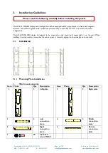
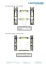
Page 10: ...ion plate PANEL CENTER LINE HORIZONTAL PANEL CENTER LINE HORIZONTAL Step2 Install the right plate with connection plate PANEL CENTER LINE HORIZONTAL PANEL CENTER LINE HORIZONTAL Use 16pcs M3X12 screw...

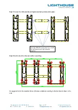
Page 11: ...RIZONTAL PANEL CENTER LINE HORIZONTAL PANEL CENTER LING VERTICAL PANEL CENTER LING VERTICAL Step4 Double check the dimension after assembling PANEL CENTER LINE HORIZONTAL PANEL CENTER LINE HORIZONTAL...

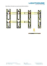
Page 12: ...F 852 2423 1092 info lighthouse tech com www lighthouse tech com Step5 Remove the bottom connection plate after installation PANEL CENTER LINE HORIZONTAL PANEL CENTER LINE HORIZONTAL PANEL CENTER LIN...

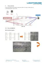
Page 13: ...F 852 2423 1092 info lighthouse tech com www lighthouse tech com 2 Screen assembly a First the 8 PCS fixed screw behind the box are assembled to the box and locked with tools b The following figure is...

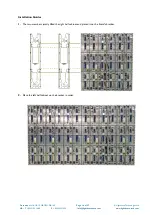
Page 14: ...nologies Ltd HK T 852 2192 1688 F 852 2423 1092 info lighthouse tech com www lighthouse tech com Installation Guides 1 The two members jointly lifted the right half cabinet and placed it on the Stand...

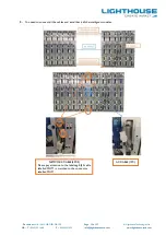
Page 15: ...1688 F 852 2423 1092 info lighthouse tech com www lighthouse tech com 3 You need to connect all the cables and install back all the intelligent modules NETWORK CABLE 4PCS Please pay attention to the...

Page 16: ...3 1092 info lighthouse tech com www lighthouse tech com 4 The cabinet is combined by sliding on the wall mount we must make sure that the steel block is properly connected to the positioning 5 After t...

Page 17: ...1092 info lighthouse tech com www lighthouse tech com 6 Install and tighten 8 pcs black M4 flat head screws to both top and bottom side of the case 7 Install M4 screws 4 PCS M4 screws 4 PCS M4 screws...

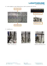
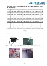
Page 18: ...om 8 All the intelligent modules LED Panel have labels stuck on the back side Please follow below number to install back the intelligent modules Install the Sensor Box 1 Take out a sensor box Run the...

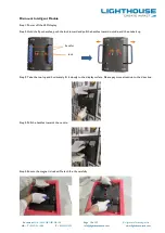
Page 19: ...t Module Step1 Power off the LED display Step2 Hold the 2pcs handles push the lock inward and pull the handles toward outside and then take it up Step3 Take the tool up and horizontaly fit it closely...

Page 20: ...a spare intelligent module and locate the intelligent module to case please pay attention to the arrow direction on the back side of it Step2 Flatten the intelligent module Note When mounting an inte...

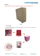
Page 21: ...ighthouse tech com www lighthouse tech com Packaging NOTE The pictures are schematic diagrams Everything is subject to the infact products Carton 1 Pack up the IMs Pack up six intelligent modules into...

Page 22: ...OB OPM DR 1 00 Page 22 of 37 Lighthouse Technologies Ltd HK T 852 2192 1688 F 852 2423 1092 info lighthouse tech com www lighthouse tech com 2 Pack up the mounting plate 3 Pack up the cabinet and put...

Page 23: ...ausing unnecessary disconnection of the supply and be able to detect excess currents due to faults within the equipment during normal operation 3 2 4 Earthing Each panel is separately connected to the...

Page 24: ...eutral Green Yellow AC Protective earth AC Protective earth 3 3 2 Number of Power Cords 1 Countries using 110V AC The product contains two input power supply cords intended for connection with two ind...

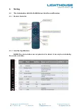
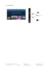
Page 25: ...852 2423 1092 info lighthouse tech com www lighthouse tech com 4 Setting 4 1 The Introduction of A136 15 OB Screen Interface and Function 4 1 1 Remote Controller 4 1 2 Interface Specifications NOTE Th...

Page 26: ...Document LH A136 15 OB OPM DR 1 00 Page 26 of 37 Lighthouse Technologies Ltd HK T 852 2192 1688 F 852 2423 1092 info lighthouse tech com www lighthouse tech com 4 1 3 Connection...

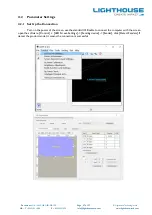
Page 27: ...com www lighthouse tech com 4 2 Parameter Settings 4 2 1 Set Up the Connection Turn on the power of the screen use the standard USB cable to connect the computer with the screen open the software Cont...

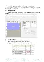
Page 28: ...use the standard USB cable to connect the PC and control the LED display through the gigabit network port 4 2 3 Parameter Settings Connect the PC to the display screen successfully the screen paramet...

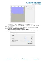
Page 29: ...can be set to the main screen PIP1 PIP2 at most the main screen and PIP1 PIP2 can be displayed at the same time Screen adjustment can adjust the color saturation brightness compensation and contrast o...

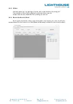
Page 30: ...be used connections from the sending card The parameters of the software adjustment can be imported or exported All parameters become default after factory Settings are restored 4 2 6 Detect the Recei...

Page 31: ...Make sure the IM is firmly mounted as which will affect the water resistance ability of the front panel 7 Power on the panel 8 Please make sure the replaced IM is functioning well Appendix B Trouble S...

Page 32: ...the corresponding position 3 PSU problems The abnormal module position of IM is not bright the state of the PSU in the corresponding position is power supply abnormally Inspection Replace the PSU in...

Page 33: ...particularly bright when the screen is white unlike others Inspection Switch calibration off again then switch to calibration on to confirm the existence of calibration data You can also switch IMs da...

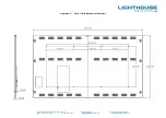
Page 34: ...ocument LH A136 15 OB OPM DR 1 00 Page 34 of 37 Lighthouse Technologies Ltd HK T 852 2192 1688 F 852 2423 1092 info lighthouse tech com www lighthouse tech com Appendix C A136 15 OB Mechanical Assembl...

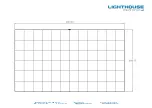
Page 35: ...Document LH A136 15 OB OPM DR 1 00 Page 35 of 37 Lighthouse Technologies Ltd HK T 852 2192 1688 F 852 2423 1092 info lighthouse tech com www lighthouse tech com...

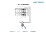
Page 36: ...ocument LH A136 15 OB OPM DR 1 00 Page 36 of 37 Lighthouse Technologies Ltd HK T 852 2192 1688 F 852 2423 1092 info lighthouse tech com www lighthouse tech com Appendix D A136 15 OB Data Wiring Diagra...

Page 37: ...cument LH A136 15 OB OPM DR 1 00 Page 37 of 37 Lighthouse Technologies Ltd HK T 852 2192 1688 F 852 2423 1092 info lighthouse tech com www lighthouse tech com Appendix E A136 15 OB Power Wiring Diagra...

Reviews: