background image

Index

5HY

I-3

Operation MASS mode 5-1
Operation Mode 4-2, 5-3
Options 4-26, 5-23

P

Package Contents 3-1
Particle Display 4-19, 5-16
Power 2-3, 4-4, 5-5
Power On Password 4-33, 4-34, 5-30, 5-31
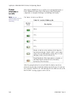
Power Shutdown Levels 4-49, 5-46
Preventive Maintenance 6-1
Print Cumulative Data 4-32
Print Last Record 4-5, 5-6
Print Model Name 4-32, 5-29
Print On Alarm 4-32, 5-29
Print On Sample 4-32, 5-29
Print Record Button 4-45, 5-41
Print Separator 4-32, 5-29
Print Serial Number 4-32, 5-29
Print Setup 4-32, 5-29

Print Cumulative Data 4-32
Print Model Name 4-32, 5-29
Print On Alarm 4-32, 5-29
Print On Sample 4-32, 5-29
Print Separator 4-32, 5-29
Print Serial Number 4-32, 5-29

Printer

Optional 2-2

Printer Options 4-32, 5-29
Printing

From MAIN Screen 4-5, 5-6
Last Record 4-5, 5-6

Printing Buffer Report 4-47, 5-43

R

Raw 4-19
Recipe Button 4-5
Removing the Battery 3-7

S

Safety 1-1, 6-1

General 1-1

Laser 1-1

Sample 4-14, 5-13
Sample Setting 4-17, 5-16

Count Mode 4-17, 5-16

Sample Time 4-6, 4-15, 5-7, 5-14
Sample Timing 4-14, 5-13
Sample Volume 4-16, 5-14
Security 4-33, 5-30
Select Location 4-5, 5-6
Service 4-35, 5-32
Service Indicator 4-6, 5-7
Specifications 2-2
Start/Stop Button 4-7, 5-8
Storage Temp/RH 2-3
Summary Report 4-46, 5-43
Supporting Software 2-2

T

Touch Screen Display 2-2
Touch Screen Overview 4-2, 5-3

U

Unpacking the Counter 3-1
Using the Counter

First Use 4-1, 5-2

V

Vacuum Source 2-2
Verify Touch Screen Alignment 5-25
View Buffer

Alarm Status 4-44, 5-41
Analog Data 4-45, 5-41
Flow Status 4-44, 5-41
Laser Status 4-45, 5-41
Print Record 4-45, 5-41

View Buffer Screen 4-43, 5-39
Viewing Analog Data 4-45, 5-41

W

Warranty A-1

Summary of Contents for Handheld 3016 IAQ

Page 1: ...OPERATING MANUAL Handheld3016IAQ P A R T I C L E C O U N T E R...

Page 2: ...00...

Page 3: ...Lighthouse Worldwide Solutions HANDHELD 3016 IAQ Particle Counter Gen E Operating Manual...

Page 4: ...not permitted to disclose or allow to be disclosed such information except as permitted in writing by Lighthouse Worldwide Solutions The information contained herein is subject to change without noti...

Page 5: ...l and Laboratory Use Part1 General Requirements LASER SAFETY IEC 60825 1 Am 2 Guidance on Laser Products Conforms to IEC 60601 2 22 FDA 21 CFR Chapter 1 Subchapter J Laser Notice 50 EMC EN61326 Electr...

Page 6: ......

Page 7: ...n 3 1 Accessories 3 1 Prepare Instrument for Use 3 2 Power Requirements 3 2 Install the Battery 3 3 Connect Power 3 6 Battery Removal 3 7 Optional Printer Accessory 3 9 Connecting to an External Compu...

Page 8: ...ALIGN TOUCH SCREEN 4 26 Autostart Mode 4 29 Pump Startup 4 29 LANGUAGE 4 30 COMM ADDRESS 4 31 OUTPUT SETUP 4 32 SECURITY 4 33 POWER ON PASSWORD 4 34 CONFIGURATION PASSWORD 4 34 SERVICE 4 35 STATUS 4...

Page 9: ...LOCK 5 21 OPTIONS 5 23 CONTRAST ADJUST 5 23 AUDIBLE BEEP ADJUST 5 23 ALIGN TOUCH SCREEN 5 23 Autostart Mode 5 26 Pump Startup 5 26 LANGUAGE 5 27 COMM ADDRESS 5 28 OUTPUT SETUP 5 29 SECURITY 5 30 POWER...

Page 10: ...3016 IAQ Gen E Operating Manual t iv 5HY Appendix A Limited Warranty Limitation Of Warranties A 1 Warranty Of Repairs After Initial Two 2 Year Warranty A 1 Appendix B Default Settings HANDHELD Default...

Page 11: ...l injury damage to the instrument or loss and or improper storage of data boldface Introduces or emphasizes a term Courier font Indicates command syntax or text displayed by the diagnostic terminal Bo...

Page 12: ...Lighthouse HANDHELD 3016 IAQ Gen E Operating Manual ii 5HY...

Page 13: ...Health and Safety Act of 1968 when used under normal operation and maintenance Service procedures on the sensor can result in exposure to invisible radiation Service should be performed only by facto...

Page 14: ...Lighthouse HANDHELD 3016 IAQ Gen E Operating Manual 1 2 5HY...

Page 15: ...Particles scatter light from the laser diode The collection optics collect and focus the light onto a photo diode that converts the bursts of light into electrical pulses The pulse height is a measur...

Page 16: ...Particle Mode Concentration manual automatic beep cumulative differential Count Modes MASS Mode Mass Concentration PM Data Storage Up to 3000 sample records includes particle environmental data plus...

Page 17: ...r unit continues to perform within specification Power Unit 12VDC AC DC Adapter 100 240V 50 60Hz Battery Li Ion removable and rechargeable Dimensions 8 75 L x 5 0 W x 2 5 H 22 23 x 12 7 x 6 35 cm Weig...

Page 18: ...Lighthouse HANDHELD 3016 IAQ Gen E Operating Manual 2 4 5HY...

Page 19: ...anything is missing from the above list please contact your sales representative at Lighthouse Worldwide Solutions immediately at 1 800 945 5905 or techsupport golighthouse com WARNING Do not ship the...

Page 20: ...4 Have advanced reporting with standard reports and much more Please contact Lighthouse Worldwide Solutions at 800 945 5905 USA Toll Free or 541 770 5905 Outside of USA for details Prepare Instrument...

Page 21: ...uctions 1 Make sure that the power switch is in the OFF position and the instrument s power adapter is not connected 2 Open the battery compartment by sliding the battery compartment door on the botto...

Page 22: ...o the compartment on top of the release ribbon Push the battery fully into the compartment until it connects and is entirely inside the battery compartment as shown in Figure 3 3 Figure 3 3 Insert bat...

Page 23: ...so that it is flush with the bottom of the HANDHELD See Figure 3 5 Figure 3 5 Close the Battery Compartment door 7 Slide the battery compartment door to the right until it clicks and latches as shown...

Page 24: ...power plug into its receptacle on the left side of the HANDHELD See Figure 3 7 Figure 3 7 DC power plug 2 Push the connector in until fully seated as shown in Figure 3 8 Figure 3 8 Inserting DC power...

Page 25: ...sliding the door to the left to unlatch it as shown in Figure 3 9 Figure 3 9 Unlatch Battery Compartment door Note Remove the battery if the instrument will be stored for a month or longer Leaving th...

Page 26: ...IAQ Gen E Operating Manual 3 8 5HY 3 Hold the instrument securely then pull the battery release ribbon outward to disconnect the battery and slide the battery out Remove the battery See Figure 3 11 Fi...

Page 27: ...ptional external thermal printer can be used with the HANDHELD to print reports directly from the instrument Connect the external printer as illustrated in the printer Read Me First document 248083378...

Page 28: ...iew Note The DATA port can be used for the printer or to connect HANDHELD to an external computer It cannot be used to connect to both at the same time 1 To connect to the HANDHELD insert the RJ 45 en...

Page 29: ...urate data Contact Lighthouse for more information 1 Insert the battery included with the shipment see Chapter 2 for instructions 2 Position the instrument in the environment to be measured 3 Remove t...

Page 30: ...f each particle 11 If the instrument is in AUTO mode with cycles and a hold time HOLDING will display after each cycle and FINISHED will display when all the cycles are complete 12 Press the STOP butt...

Page 31: ...ration Particle Mode 5HY 4 3 Menu Map Particle Mode This interface allows the user to view and configure the instrument to specific needs and applications See Figure 4 2 Figure 4 2 Menu Map Particle M...

Page 32: ...e powered by an external power supply or from a removable battery When a battery is used the battery indicator will show the level of the battery charge remaining See Figure 4 3 Figure 4 3 MAIN Screen...

Page 33: ...ppears in the battery indicator the pump will automatically stop to prevent the battery from discharging completely Battery Indicator Indicates that the instrument is being powered by a rechargeable b...

Page 34: ...e 1 3 indicates that the last completed count was the first of three samples to be recorded at this location The maximum number of cycles is 999 When set to 0 the unit will run in Auto mode continuous...

Page 35: ...this time the word STARTING will display START STOP Press START button on the screen to start counting When sampling the instrument will display COUNTING in the lower right portion of the screen as s...

Page 36: ...le arrows will move the cursor up and down by a single line Locations can also be selected by touching the location name on the screen The AUTO INC button when activated will allow the user to advance...

Page 37: ...Operation Particle Mode 5HY 4 9 Zoomed Data View Press anywhere in the Particle Data area to display the Zoomed view as shown in Figure 4 8 Figure 4 8 Zoomed Data View...

Page 38: ...ght side bar Figure 4 9 Zoomed Data View Buttons When the instrument is STOPPED or HOLDING press anywhere in the white data area to return back to the MAIN screen START or STOP counting Display Partic...

Page 39: ...rd parameters sample settings enable disable alarms and thresholds and clear the data buffer Device Setup includes buttons to configure the instrument s date and time set the LCD contrast adjust the i...

Page 40: ...ius by pressing the ANALOG button on the Configuration screen The Select Temperature Units window displays There are two buttons on the Select Temperature Units window The button displayed shows the u...

Page 41: ...s shown in Figure 4 14 Figure 4 14 Analog data on MAIN screen When the unit is not counting or when it is holding you can zoom on the instrument s current Analog data display Press anywhere in the Par...

Page 42: ...the number of desired cycles using the numeric keypad on the right Press ERASE to erase a number if needed Press ENTER to set the Cycles DELAY The Initial Start Delay hh mm ss is the time between pre...

Page 43: ...eded Press ENTER to set the Hold Time Note If the Hold time is greater than one minute the pump will shut off during the specified hold time HOLD The Hold Time hh mm ss is the time between count cycle...

Page 44: ...me in cubic feet ft3 cubic meters m3 or liters l When this is set the corresponding Sample Time will automatically be set See Figure 4 17 Figure 4 17 Changing Sample Volume unit of measure Note If the...

Page 45: ...y according to the Sample Time Hold Time and the number of Cycles that are configured If Cycles are set to 0 the instrument will continue indefinitely in Auto Mode until the STOP button is pressed MAN...

Page 46: ...te BEEP mode only works with CUMULATIVE data If alarming is enabled on more than one channel size only the smallest channel size will be used to trigger the alarm in BEEP mode Larger channel sizes wil...

Page 47: ...is selected DIFF or CUML The data format is either Raw RAW or Normalized NORM Raw data displays the actual number of particles counted Normalized data shows particle concentrations calculated from the...

Page 48: ...o the cumulative counts To enable the alarming for any channel press the X next to that channel When a checkmark is displayed that channel is enabled for alarming Press the checkmark to disable the al...

Page 49: ...ion screen or press MAIN to return to the MAIN screen Figure 4 21 MAIN screen with 2 channels enabled for alarming Note To receive alarms the Sample Time must be greater than 1 second When a particle...

Page 50: ...in the sample period When the instrument beeps in response to the Alarm and Threshold settings it can be silenced by tapping anywhere on the screen while the unit is sampling After acknowledging the a...

Page 51: ...s address setting print options enabling password restrictions viewing the instrument s current status and or with proper authorization adjust service settings See Figure 4 24 Figure 4 24 Device Setup...

Page 52: ...format by pressing the M D Y button to display the date with the month first Alternatively press the D M Y button to display the Date with the day first or press the Y M D button to display the date...

Page 53: ...pressing the TIME button as shown in Figure 4 28 Figure 4 28 Configuring TIME Enter the desired Time in hours minutes and seconds then press ENTER to save the new time Press BACK to return to the Con...

Page 54: ...T The contrast brightness of the LCD screen can be adjusted by pressing the first set of UP and DOWN arrows AUDIBLE BEEP ADJUST The audio level of the BEEP can be adjusted by pressing the second set o...

Page 55: ...ng this process you will align the screen incorrectly The following screen appears Touch the circle in the lower left corner as shown in Figure 4 30 Figure 4 30 Alignment Step 1 Note Using a PDA Stylu...

Page 56: ...ating Manual 4 28 5HY Touch the circle in the lower right corner as shown in Figure 4 32 Alignment Step3 Press anywhere inside the rectangle to when you are ready to complete aligning the screen See F...

Page 57: ...e instrument is powered on or regains power after a power outage the instrument will immediately begin sampling based its configured mode delay start and hold times Pump Startup This is ON by default...

Page 58: ...5HY LANGUAGE Pressing the LANGUAGE button allows the user to change the operating language displaying the screen shown in Figure 4 35 Figure 4 35 Operating Language Selection Screen Press the desired...

Page 59: ...ddress specified on the Communication screen shown below COMM addresses range from 1 to 63 For RS 485 communications each device on a multi port chain must have a unique address Figure 4 36 COMM Addre...

Page 60: ...ion Model Name When enabled the Model name of the instrument will print in the header of all printouts Serial Number When enabled the Serial Number of the instrument will print in the header of all pr...

Page 61: ...guration password is enabled the user will be required to enter the correct password to access the Configuration screen To set the password for the POWER ON select the POWER ON button then type in a p...

Page 62: ...re that a password must be entered before the instrument can be used enable the POWER ON password See Figure 4 39 Figure 4 39 POWER ON Password Access Screen When the POWER ON password is enabled you...

Page 63: ...Providers only The correct service password must be entered to access this area STATUS Touching the STATUS button displays the instrument programmed version of the various firmware modules This infor...

Page 64: ...settings for sampling and reports in a database that can store up to 50 recipes Selecting the ADD button displays the RECIPE text screen See Figure 4 43 The recipe can be named using up to 12 charact...

Page 65: ...shown in Figure 4 44 Each option allows the user to configure the instrument to the current recipe Figure 4 44 Recipe Configuration Press the BACK button to save the settings and return to the RECIPE...

Page 66: ...46 Figure 4 46 Recipe Analog Output Settings Pressing the EDIT button on the main RECIPE screen will allow the user to change settings on the highlighted recipe The LOAD and UNLOAD buttons add or rem...

Page 67: ...arrows or by touching the location name on the screen The following options can be enabled to configure locations for the HANDHELD When enabled the Auto Increment option will automatically select the...

Page 68: ...ion can still be used with the current settings Figure 4 48 Location Load Recipe If a recipe is loaded and a location is selected that is not associated with a recipe the user is given the option to u...

Page 69: ...the Configuration screen or the MAIN button to return to the MAIN screen Activating the AUTO INC button allows the user to select the next location once the number of cycles is completed The user is p...

Page 70: ...be record 1 If the Particle Volume is set to ft3 then the concentration data will display and print in ft3 If the Particle Volume is set to m3 or Liters L then the concentration data will display and...

Page 71: ...the UP and DOWN arrow buttons The single arrow moves one record at a time Figure 4 52 Data Screen Normalized data in ft3 Figure 4 53 Data Screen Normalized data in m3 The Data screen displays the foll...

Page 72: ...n this column indicates raw counts while ft3 and m3 indicate normalized counts Loc Indicates the location at which the data record was recorded The Location name listed is the alphanumeric label that...

Page 73: ...this command to print the Mass Concentration data PRINT RECORD When you push the PRINT RECORD button whatever record is currently displayed in the Data screen will print as a single sample record The...

Page 74: ...lue Average Standard Deviation The UCL calculation will be printed for each channel size if the num ber of locations in the range is 2 through 9 The calculation will only print if the Format settings...

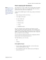
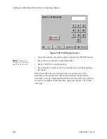
Page 75: ...button The following screen will display See Figure 4 55 Figure 4 55 Print Range Screen Enter the number of records to print and press the ENTER button Note Printing ALL records may take some time if...

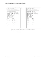
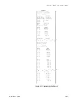
Page 76: ...1 cfm Laser OK TEMP 66 77 F RH 35 71 Particles ft 3 Size Cumul 0 3 4260 0 0 5 810 0 1 0 580 0 3 0 360 0 5 0 350 0 10 0 310 0 Location LOC003 Particles ft 3 Summary Cuml of samples 2 Size Max 0 3 4260...

Page 77: ...the battery reaches its critical low point the instrument will shut down all power To prevent loss of power attach the AC cord and plug into an outlet as soon as the BATT LOW message appears on the s...

Page 78: ...Lighthouse HANDHELD 3016 IAQ Gen E Operating Manual 4 50 5HY...

Page 79: ...y allows the user to operate the instrument in either Particle or Mass Concentration mode without having to flip back and forth between chapters The primary differences found in Mass Concentration mod...

Page 80: ...d outside the environment being measured 4 The included Temperature Relative Humidity probe can be attached to the provided receptacle to read environmental data 5 Set on off switch found on the left...

Page 81: ...and configure the instrument Operation Mode Two modes of operation are available on the HANDHELD 3016 IAQ The mode is chosen by toggling the PARTICLE MASS button circled in Figure 5 1 This chapter ass...

Page 82: ...Q Gen E Operating Manual 5 4 5HY Menu Map Mass Concentration Mode This interface allows the user to view and configure the instrument to specific needs and applications See Figure 5 2 Figure 5 2 Menu...

Page 83: ...by an external power supply or from a removable battery When a battery is used the battery indicator will show the level of the battery charge remaining See Figure 5 3 Figure 5 3 MAIN Screen battery...

Page 84: ...when the X appears in the battery indicator the pump will automatically stop to prevent the battery from discharging completely Battery Indicator Indicates that the instrument is being powered by a re...

Page 85: ...was the first of three samples to be recorded at this location The maximum number of cycles is 999 When set to 0 the unit will run in Auto mode continuously until the STOP button is pressed SAMPLE Th...

Page 86: ...shown in Figure 5 6 Figure 5 6 Main Screen Counting mode Press the STOP button to stop counting the word STOPPED will display MASS PARTICLE Button Pressing the MASS PARTICLE button changes the operat...

Page 87: ...ations can also be selected by touching the location name on the screen Recipes associated with a specific location may also be loaded when that location is selected The AUTO INC button when activated...

Page 88: ...e record parameters sample settings thresholds enable disable alarms and clear the data buffer Device Setup includes buttons to configure the instrument s date and time set the LCD contrast adjust the...

Page 89: ...essing the ANALOG button on the Configuration screen The Select Temperature Units window displays There are two buttons on the Select Temperature Units window The button displayed shows the units that...

Page 90: ...Q Gen E Operating Manual 5 12 5HY Temperature and relative humidity values appear on the MAIN screen with the units you selected The values are updated in real time as shown in Figure 5 12 Figure 5 12...

Page 91: ...er of desired cycles using the numeric keypad on the right Press ERASE to erase a number if needed Press ENTER to set the Cycles DELAY The Initial Start Delay hh mm ss is the time between pressing the...

Page 92: ...me hh mm ss is the time between count cycles when the instrument is not counting particles Note The maximum Sample Time is 23 59 59 SAMPLE The Sample Time hh mm ss is the duration of one counting cycl...

Page 93: ...it of measure Press BACK to return to the Configuration screen or press MAIN to return to the MAIN screen Note If the particle volume is liters or m 3 sample volume is displayed in liters If the parti...

Page 94: ...STOP button is pressed MANU Manual Mode When the instrument is in Manual Mode it will start counting when START is pressed and stop at the end of one programmed Sample Time PARTICLE Display The data...

Page 95: ...ls enabled Note Alarming is only applicable for AUTO and MANUAL mode It applies only to Raw particle counts even if the instrument is displaying Normalized data To enable the alarming for any channel...

Page 96: ...e desired alarm threshold for the selected particle channel in number of particles then press ENTER The threshold value will be updated on the Particle Alarm screen as shown in Figure 5 18 Note Alarms...

Page 97: ...m Acknowledge Note If alarms are enabled on two channels when the user presses the Alarm Acknowledge button after the first channel goes into alarm the alarm will not sound if the second channel s thr...

Page 98: ...reen without clearing the data DEVICE SETUP Device Setup includes setting the instrument s date and time adjusting the instrument s LCD contrast or beep volume aligning the touchscreen enabling autost...

Page 99: ...tering values for the desired month day and year and then press the ENTER button Note M D Y is the default date format Change the Date s format by pressing the M D Y button to display the date with th...

Page 100: ...rst Set the instrument s Time by pressing the TIME button as shown in Figure 5 25 Figure 5 25 Configuring TIME Enter the desired Time in hours minutes and seconds then press ENTER to save the new time...

Page 101: ...trast brightness of the LCD screen can be adjusted by pressing the first set of UP and DOWN arrows AUDIBLE BEEP ADJUST The audio level of the BEEP can be adjusted by pressing the second set of UP and...

Page 102: ...elsewhere during this process you will align the screen incorrectly The following screen appears Touch the circle in the lower left corner as shown in Figure 5 27 Note Using a PDA Stylus may give more...

Page 103: ...5 Touch the circle in the lower right corner See Figure 5 29 Figure 5 29 Alignment Step 3 Press anywhere inside the rectangle to when you are ready to complete aligning the screen See Figure 5 30 Figu...

Page 104: ...is enabled and the instrument is powered on or regains power after a power outage the instrument will immediately begin sampling based its configured mode delay start and hold times Pump Startup This...

Page 105: ...AGE Pressing the LANGUAGE button allows the user to change the operating language displaying the screen shown in Figure 5 32 Figure 5 32 Operating Language Selection Screen Press the desired language...

Page 106: ...by the COMM Address specified on the Communication screen shown below COMM addresses range from 1 to 63 For RS 485 communications each device on a multi port chain must have a unique address Figure 5...

Page 107: ...ny sample that experiences an alarm condition Model Name When enabled the Model name of the instrument will print in the header of all printouts Serial Number When enabled the Serial Number of the ins...

Page 108: ...When the Configuration password is enabled the user will be required to enter the correct password to access the Configuration screen To set the password for the POWER ON select the POWER ON button th...

Page 109: ...password must be entered before the instrument can be used enable the POWER ON password See Figure 5 36 Figure 5 36 POWER ON Password Access Screen When the POWER ON password is enabled you will see...

Page 110: ...orized Service Providers only The correct service password must be entered to access this area STATUS Touching the STATUS button displays the instrument programmed version of the various firmware modu...

Page 111: ...for sampling and reports in a database that can store up to 50 recipes Selecting the ADD button displays the RECIPE text screen See Figure 5 40 The recipe can be named using up to 12 characters Note...

Page 112: ...CFG screen as shown in Figure 5 41 Each option allows the user to configure the instrument to the current recipe Figure 5 41 Recipe Configuration Press the BACK button to save the settings and return...

Page 113: ...e 5 43 Recipe Analog Output Settings Pressing the EDIT button on the main RECIPE screen will allow the user to change settings on the highlighted recipe The LOAD and UNLOAD buttons add or remove the h...

Page 114: ...e UP and DOWN arrows or by touching the location name on the screen The following options can be enabled to configure locations for the HANDHELD When enabled the Auto Increment option will automatical...

Page 115: ...till be used with the current settings Figure 5 45 Location Load Recipe If a recipe is loaded and a location is selected that is not associated with a recipe the user is given the option to unload the...

Page 116: ...to return to the Configuration screen or the MAIN button to return to the MAIN screen Activating the AUTO INC button allows the user to select the next location once the number of cycles is completed...

Page 117: ...h will not necessarily be record 1 Note PARTICLE data may be printed even if the data was taken in MASS mode On the MAIN Screen press the MASS button which changes it to PARTICLE Return to the Data Sc...

Page 118: ...Mass Concentration of the 10 0 m channel is not included It is however included in the TPM value see TPM below Figure 5 48 can be used to aid understanding of PM Note that the 1 0 value 6 41 is the su...

Page 119: ...ata record was recorded possible laser states include OK or SRVC If the laser needs to be serviced it will print as Laser Service If laser state is SRVC please contact Lighthouse Technical Support at...

Page 120: ...Location LOC001 03 01 2007 15 51 57 Sample Time 00 00 10 Laser OK TEMP 74 7 F RH 52 2 PM Values Size PM 0 5 3 90 1 0 5 74 2 5 6 84 5 0 9 77 10 0 14 45 TPM 25 54 HH 3016 IAQ Serial 070244001 Location...

Page 121: ...amples in the report For each channel size Maximum Value Minimum Value Average Standard Deviation The UCL calculation will be printed for each channel size if the number of locations in the range is 2...

Page 122: ...ull Press ALL to print all records in the buffer Press CANCEL to cancel printing Press BACK to return to the View Buffer screen without printing the report When more than one record is printed a secon...

Page 123: ...ser OK TEMP 66 77 F RH 35 71 Particles ft 3 Size Cumul 0 3 4260 0 0 5 810 0 1 0 580 0 3 0 360 0 5 0 350 0 10 0 310 0 Location LOC003 Particles ft 3 Summary Cuml of samples 2 Size Max 0 3 4260 0 0 5 81...

Page 124: ...level and before the battery reaches its critical low point the instrument will shut down all power To prevent loss of power attach the AC cord and plug into an outlet as soon as the BATT LOW message...

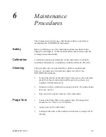
Page 125: ...This procedure may be superceded by customer requirements however not under any circumstances apply Acetone to the HANDHELD instrument 1 To keep the interior of the instrument clean remove the isokine...

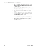
Page 126: ...nd set a 10 second hold 6 Set Cycles to 10 so the instrument will take 10 five minute samples 7 If an average of more than one count per five minute sample is reported reset the instrument to sample f...

Page 127: ...remedies granted under this Section may at LWS s option be terminated C THE FOREGOING WARRANTY IS EXCLUSIVE AND IN LIEU OF ALL OTHER REPRESENTATIONS WARRANTIES AND COVENANTS EXPRESS OR IMPLIED WITH RE...

Page 128: ...Lighthouse HANDHELD 3016 IAQ Gen E Operating Manual A 2 5HY...

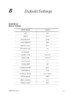
Page 129: ...LOC 001 MODE AUTO DATA DISPLAY CUML DATA FORMAT RAW PARTICLE VOL FT 3 ENVIRON UNIT US PASSWORD 0 SAMPLE TIME 00 01 00 HOLD TIME 00 00 10 OF CYCLES 10 COMM ADDR 001 AUDIBLE ALERT OFF THRESHOLD 1000 STO...

Page 130: ...Lighthouse HANDHELD 3016 IAQ Gen E Operating Manual B 2 5HY...

Page 131: ...6 C Calibration 2 2 CFG password Enabling 4 33 5 30 Changing Locations 4 8 5 9 Channel Threshold 2 2 Clear Buffer 4 22 5 20 Clock 4 23 5 21 COMM Address 4 31 5 28 Communication Modes 2 2 CONC 4 17 Con...

Page 132: ...ensors 2 2 F Features 2 1 Flow Rate 2 2 Flow Status 4 5 4 44 5 6 5 41 H HANDHELD 3016 IAQ particle counter 2 1 Hold Time 4 6 4 15 5 7 5 14 How particle counter works 2 1 How to use 4 1 5 1 I Informati...

Page 133: ...nting From MAIN Screen 4 5 5 6 Last Record 4 5 5 6 Printing Buffer Report 4 47 5 43 R Raw 4 19 Recipe Button 4 5 Removing the Battery 3 7 S Safety 1 1 6 1 General 1 1 Laser 1 1 Sample 4 14 5 13 Sample...

Page 134: ...Lighthouse HANDHELD 3016 IAQ Gen E Operating Manual I 4 5HY Warranty Of Repairs A 1 Weight 2 3 Z Zero Count Level 2 2 Zoomed Data View 4 9...

Page 135: ...00...

Page 136: ...Service and Support Tel 1 800 945 5905 USA Toll Free Tel 1 541 770 5905 Outside of USA techsupport golighthouse com www golighthouse com...

Reviews: