background image

Lighthouse REMOTE 2014P, 3014P, 5014P Operating Manual

A-12

248083408-1 Rev 1

Setting the Alarm Threshold Value

The Alarm Threshold Value is set in the low register of the channels.

Data 
Registers

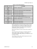
Data is stored in the input registers (30xxx series), which are read-only.  
All data items are four bytes long and are stored across two registers.
Byte and word order for particle data is big-endian.  Thus, data items 
are formed by placing the high bytes in front of the low bytes.

Example:

<High Bytes><Low Bytes> = <4 Byte Data Item>

Analog data is little-endian. Thus, analog data items are formed by 
placing the low bytes in front of the high bytes.

Example:

<Low Bytes><High Bytes> = <4 Byte Data Item>

Not all particle and analog channels are necessarily active.  Retrieving 
data from an inactive channel returns garbage.  See the Data Enable 
Registers section of this document for details on how to record data 
from active channels.

This entire series of registers represents one data record in the device.
The Record Index Register (40025) must be changed to index other 
records here.

Table A-12  Alarm Threshold Registers set to 

default value

Registers

Particle

Channel

Threshold 

Value

45009 - 45010

1

1000

45011 - 45012

2

1000

45013 - 45014

3

1000

45015 - 45016

4

1000

45017 - 45018

5

1000

45019 - 45020

6

1000

Summary of Contents for Remote 2014P

Page 1: ......

Page 2: ......

Page 3: ...Lighthouse Worldwide Solutions REMOTE 2014P 3014P 5014P Airborne Particle Counter Gen C Operating Manual...

Page 4: ...ermitted to disclose or allow to be disclosed such information except as permitted in writing by Lighthouse Worldwide Solutions The information contained herein is subject to change without notice Lig...

Page 5: ...urement Control and Laboratory Use Part 1 General Requirements LASER SAFETY Guidance on Laser Products Conforms to FDA 21 CFR Chapter 1 Subchapter 1 EMC EN61326 Electrical Equipment for Measurement Co...

Page 6: ......

Page 7: ...014P Specifications 2 5 Chapter 3 Unpacking Inspecting and Installing Initial Inspection 3 1 Unpacking 3 1 Shipping Instructions 3 2 Understanding the LEDs 3 3 Connections 3 4 Communication Ports 3 5...

Page 8: ...tion 4 1 DIP Switches 4 1 DIP Switch Settings 4 2 GENERAL DEFINITIONS 4 2 Communications Mode 4 2 REMOTE Display Mode 4 2 Addressing 4 3 Communicating with the Instrument 4 4 RS 485 Port 4 5 RS 485 Co...

Page 9: ...for a Channel A 10 Threshold Setup Registers A 11 Setting the Alarm Threshold Value A 12 Data Registers A 12 Device Status Word 30007 30008 A 14 Valid Data in Channels 30073 30076 A 15 Data Type Regi...

Page 10: ...Lighthouse REMOTE 2014P 3014P 5014P Operating Manual t iv 248083408 1 Rev 1...

Page 11: ...and warns that doing something incorrectly could result in personal injury damage to the instrument or loss and or improper storage of data boldface Introduces or emphasizes a term Courier font Indic...

Page 12: ...Lighthouse REMOTE 2014P 3014P 5014P Operating Manual ii 248083408 1 Rev 1...

Page 13: ...sensor that is a Class 1 product as defined by 21 CFR Subchapter J of the Health and Safety Act of 1968 when used under normal operation and maintenance Service procedures on the sensor can result in...

Page 14: ...Lighthouse REMOTE 2014P 3014P 5014P Operating Manual 1 2 248083408 1 Rev 1...

Page 15: ...e starting particle size sensitivity The 2014P sensitivity is 0 2 microns the 3014P sensitivity is 0 3 microns and the 5014P sensitivity is 0 5 microns Figure 2 1 REMOTE 3014P Airborne Particle Counte...

Page 16: ...manually as required Using an internal pump the instrument can be installed where space is limited The REMOTE 2014P 3014P or 5014P integrate seamlessly into large facility monitoring management syste...

Page 17: ...T Traceable Communication Modes RS 232 or RS 485 Modbus Data Storage 3000 records rotating buffer Supporting Software Lighthouse Monitoring System LMS XChange LMS Express LMS ExpressRT Environmental S...

Page 18: ...m Source Internal Vacuum Pump Calibration NIST Traceable Communication Modes RS 232 or RS 485 Modbus Data Storage 3000 records rotating buffer Supporting Software Lighthouse Monitoring System LMS XCha...

Page 19: ...tion NIST Traceable Communication Modes RS 232 or RS 485 Modbus Data Storage 3000 records rotating buffer Supporting Software Lighthouse Monitoring System LMS XChange LMS Express LMS ExpressRT Environ...

Page 20: ...Lighthouse REMOTE 2014P 3014P 5014P Operating Manual 2 6 248083408 1 Rev 1...

Page 21: ...damage before use even if the container appeared to be undamaged and 4 Any damages were reported to Lighthouse Technical Support at 1 800 945 5905 USA or 1 541 770 5905 Outside of USA before proceedin...

Page 22: ...battery and package it to ship separately refer to www golighthouse com rma for detailed instructions Remove attachments such as TRH or Isokinetic probes and package to prevent physical and ESD damag...

Page 23: ...he green FLOW LED turns on when the flow is correct The green FLOW LED will turn off if flow is insufficient The orange SERVICE LED will stay on steady if Laser power is low sensor optics are dirty or...

Page 24: ...in a rotating buffer 7 Internal pump with auto adjusting flow control Connections The top of the instrument has one connection the sampling inlet Figure 3 2 Connection on Top The REMOTE 2014P 3014P o...

Page 25: ...input ports for connecting 4 20mA analog sensors 9 USB Port Type B For point to point communications via a PC Communication Ports The RS 485 port is a dual purpose connection It is a hybrid of the MOD...

Page 26: ...RJ 12 cables The pinout of the cables is shown below Lighthouse sensors come complete with adapters and prewired cables The Lighthouse Temperature Relative Humidity sensor has both functions wired to...

Page 27: ...t the ports are oriented with the locking tabs at the side DIP Switches DIP switches 1 6 are used for addressing the instrument for RS 485 and setting the Communications Mode DIP switch 7 enables or d...

Page 28: ...eral Interface Connector An external peripheral device such as a light stick buzzer or remote control device can be connected to the back or the REMOTE P via the Peripheral Interface Connector PIC The...

Page 29: ...wer before the driver has been installed will be problematic Refer to the following 1 Remove power from the instrument 2 Connect Side B of a standard A to B USB cable See Figure 3 5 to the instrument...

Page 30: ...roducts to connect to the instrument and retrieve data from it Use the port assignment determined above Ethernet Configuration The REMOTE P comes pre configured to use DHCP and receive an IP address a...

Page 31: ...nce of the user or technician ARP Address Resolution Protocol a program that can change the ARP Cache of a host by adding or removing IP addresses Each IP address is associated to a MAC address ARP Ca...

Page 32: ...n to a PC Software Required Contact the network administrator if any of the following are not installed or not functional Windows 2000 XP Professional or Windows 7 Telnet Note All values in screen sho...

Page 33: ...it is necessary to change the instrument s Ethernet parameters to allow for easier troubleshooting When this is needed make sure the instrument is reprogrammed to its previous network settings before...

Page 34: ...rface Windows Telnet Programming 1 Start Windows 2 On the Taskbar click on Start WARNING Perform only the steps or commands as provided in this guide Failure to heed this warning can result in damage...

Page 35: ...direct communications with the instrument before an IP is programmed into its Ethernet interface 8 Type arp s xxx xxx xxx xxx nn nn nn nn nn nn and press Enter Replace the x s with the desired IP add...

Page 36: ...e screen below Figure 3 12 Telnet 9999 You will have 4 seconds to respond in the next step If you respond too slowly you ll have to repeat step 10 11 Press Enter to start the REMOTE Ethernet interface...

Page 37: ...gure 3 14 Assigning IP Address 13 Type Y to set the Gateway IP address Type the Gateway IP address and press Enter Figure 3 15 Assigning Gateway IP Address 14 Type Y to set the Netmask type the desire...

Page 38: ...r absolute security requirements If a password is applied and forgotten the instrument will have to be returned to Lighthouse to get the password cleared Figure 3 17 Telnet Config Password Screen 16 T...

Page 39: ...econds monitoring equipment and software should see the instrument and be able to retrieve data from it Contact Lighthouse Worldwide Solutions Technical Support for additional information or further a...

Page 40: ...Lighthouse REMOTE 2014P 3014P 5014P Operating Manual 3 20 248083408 1 Rev 1...

Page 41: ...MODBUS protocol is detailed in Appendix A This chapter contains the information needed to program the basic configuration for the instrument to meet your needs DIP Switches The DIP switches are behin...

Page 42: ...WARNING Always turn the instrument OFF before connecting or disconnecting the REMOTE Display If DIP switch 7 is ON but the REMOTE Display is not connected when the instrument is powered on the unit wi...

Page 43: ...0 0 1 33 0 1 0 0 0 0 2 0 1 0 0 0 1 34 1 1 0 0 0 0 3 1 1 0 0 0 1 35 0 0 1 0 0 0 4 0 0 1 0 0 1 36 1 01 0 0 0 5 1 0 1 0 0 1 37 0 1 1 0 0 0 6 0 1 1 0 0 1 38 1 1 1 0 0 0 7 1 1 1 0 0 1 39 0 0 0 1 0 0 8 0 0...

Page 44: ...ptop PC Figure 4 3 The Communications Ports Showing Pin Numbers 1 1 1 0 1 0 23 1 1 1 0 1 1 55 0 0 0 1 1 0 24 0 0 0 1 1 1 56 1 0 0 1 1 0 25 1 0 0 1 1 1 57 0 1 0 1 1 0 26 0 1 0 1 1 1 58 1 1 0 1 1 0 27 1...

Page 45: ...me of network before and after the design phase to make sure the REMOTE P and other instruments perform as expected The REMOTE P does not support a daisy chain configuration and must be used in a star...

Page 46: ...ay touchscreen interface DIP Switch 7 must be ON before connecting the Display and powering on the instrument Please consult the REMOTE Display Operating Manual LWS PN 248083285 1 for detailed informa...

Page 47: ...Delay The Location is set by writing an unsigned integer to register 40026 The range of values is from 0 to 999 Sample Time Hold Time and Initial Delay all use 2 registers a high word and a low word...

Page 48: ...nitial Delay high Works in conjunction with 40030 Number of seconds to wait before starting the first sample Max value is 359 999 which equals 99h 59m 59s 40030 unsigned integer Initial Delay low 4003...

Page 49: ...5 Enable Remote Control Locks out the instrument s user interface Can only change instrument parameters via MODBUS 6 Enable Local Control Unlocks the instrument s user interface Instrument changes ca...

Page 50: ...old time is effectively the time between a STOP and a START command After the last desired sample is taken send the following to stop the pump 8 Stop Pump AUTOMATIC Counting Mode In Automatic counting...

Page 51: ...nder any circumstances apply Acetone to the REMOTE P instrument 1 To keep the interior of the laser sensor clean remove the isokinetic probe from the air inlet and install the protective plastic cap s...

Page 52: ...0 five minute samples 7 If an average of more than one count per five minute sample is reported reset the instrument to sample for 30 minutes again to purge it then repeat the Purge Test again 8 After...

Page 53: ...Address 0 is the broadcast address Supported MODBUS Commands See www modbus org for documentation on how to use these commands Table A 1 MODBUS Communications Settings Baud Rate 19200 Data Bits 8 Stop...

Page 54: ...Status bit 0 RUNNING bit 1 SAMPLING bit 2 NEW DATA bit 3 DEVICE ERROR 40004 unsigned integer Firmware version Major version digits are hundreds Minor version digits are tens and ones For example 210...

Page 55: ...he Universal Manifold and values 1 6 for the MiniManifold Controller moves the arm to that position on the manifold Value 0 moves arm to Home position 40027 signed integer Real Time Clock RTC high Dis...

Page 56: ...lts 40047 signed integer Calibration Due Date high Indicates when instrument is due for calibration this number can be generated by the ANSI C C time function 40048 signed integer Calibration Due Date...

Page 57: ...tional threshold alarming channel bit set if threshold exceeded for that given channel Alarm Parameter 40038 defines additional parameters that may be needed in defining an alarm mode 40203 ASCII stri...

Page 58: ...the name for location 3 would be located at registers 40204 40205 If Bit 3 is of Register 40500 is 0 up to 200 locations can be specified Registers 40200 40999 are reserved for eight character names...

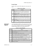
Page 59: ...1 to indicate that a new data record has been recorded and it hasn t been read via modbus yet When a data record has been read via modbus registers 30001 to 30999 then this flag is reset to zero 3 DEV...

Page 60: ...nual Stop command If applicable to device does not start pump 10 Manual Stop Stops sampling Records count since Manual Start 11 Instrument Start Automatic Counting Particle Counters Uses defined Initi...

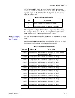
Page 61: ...w word for particle channel 1 Table A 8 Enable Disable Bits Bit Description 0 DATA ENABLE 0 disable 1 enable 1 ALARM ENABLE 0 disable 1 enable Table A 9 Alarm Enable Registers Register Data Type Descr...

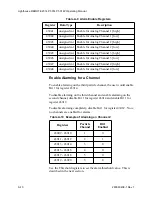
Page 62: ...shold value This is described in the next section 43041 unsigned int Enable for Analog Channel 1 high 43042 unsigned int Enable for Analog Channel 1 low 43043 unsigned int Enable for Analog Channel 2...

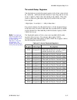
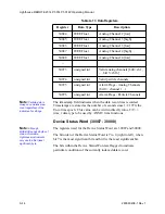
Page 63: ...9 position The threshold registers 45xxx series run in parallel with the data registers 30xxx series For example data register 30010 s corresponding threshold register would be 45010 Data register 300...

Page 64: ...le endian Thus analog data items are formed by placing the low bytes in front of the high bytes Example Low Bytes High Bytes 4 Byte Data Item Not all particle and analog channels are necessarily activ...

Page 65: ...ce Status high 30008 unsigned integer Device Status low 30009 unsigned integer Particle Channel 1 high 30010 unsigned integer Particle Channel 1 low 30011 unsigned integer Particle Channel 2 high 3001...

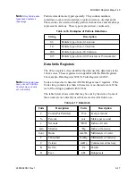
Page 66: ...sed for the Device Status Word are 30007 and 30008 The bit order of the Device Status Word is 7 to 0 right to left where bit 7 is the most significant bit and bit 0 is the least significant bit The bi...

Page 67: ...0075 represents the flag bits corresponding to analog channels that have exceeded the threshold Threshold High Registers 45xxx series based on alarm mode Register 30076 represents the flag bits corres...

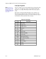
Page 68: ...Data Register 30041 s Data Type register is 41041 Data Types are assigned 4 ASCII characters across 2 registers If a Data Type string contains less than 4 characters then the rest of the string is pad...

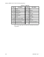
Page 69: ...ored as 4 character ASCII strings across 2 registers If the Units string contains less than 4 characters or no characters at all the rest of the string is padded with NULLs The table below shows units...

Page 70: ...Bar Bar ft 2 Square feet mBar Milli bar m 2 Square meters V Volts ft 3 Cubic feet mV Milli volts m 3 Cubic meters A Amperes L Liters mA Milli amps CFM Cubic feet per minute Ohm Ohms CMM Cubic meters p...

Page 71: ...is time allows the unit to warm up and purge any residual particles that might be inside it 5 Configure the unit to sample for 5 minutes 6 Allow the instrument to sample 6 five minute periods 7 If the...

Page 72: ...Lighthouse REMOTE 2014P 3014P 5014P Operating Manual B 2 248083408 1 Rev 1...

Page 73: ...ll warranties and remedies granted under this Section may at LWS s option be terminated C THE FOREGOING WARRANTY IS EXCLUSIVE AND IN LIEU OF ALL OTHER REPRESENTATIONS WARRANTIES AND COVENANTS EXPRESS...

Page 74: ...Lighthouse REMOTE 2014P 3014P 5014P Operating Manual C 2 248083408 1 Rev 1...

Page 75: ...A 12 C Clear LAT 3 19 Clear the Data Buffer 4 9 Clearing the Address Table 3 15 Clearing the ARP Cache 3 19 CMD 3 14 Command Console 3 14 Command Register A 7 Communicating with the Instrument 4 4 Com...

Page 76: ...9 Host 3 11 I Instrument Control 4 9 Instrument Start 4 9 IP 3 15 IP Address 3 11 IP address 3 12 L LAN 3 11 LAN topology 3 5 4 5 Laser Source 2 5 Lighthouse Monitoring System 3 19 Limitation Of Warra...

Page 77: ...ow Rate 2 4 Laser Source 2 4 Operating Temp RH 2 4 Power Requirement 2 4 Power Supply Input 2 4 Size Range 2 4 Storage Temp RH 2 4 Supporting Software 2 4 Vacuum Source 2 4 Weight 2 4 Zero Count Level...

Page 78: ...orting Software 2 3 T TCP IP 3 12 Telnet 3 12 Telnet 1 3 15 Telnet 9999 3 16 Telnet Config Password Screen 3 18 Telnet Programming 3 14 Text conventions 1 i Threshold Setup Registers A 11 Setting the...

Page 79: ......

Page 80: ......

Reviews: