Get Started
248083401-1 Rev 5
3-9
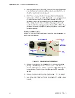
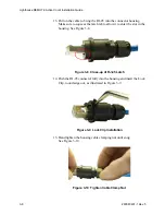
16. Install the sealing ring onto the front of the connector housing. This
seal is held in place when the connector is locked onto the
instrument. See Figure 3-11.
Figure 3-11 Install Connector Seal
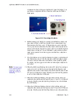
17. Slide the large lock ring down the cable and over the cable housing
body. It may need a twisting action to fully position it against its
retainer ring. Verify that its larger opening is facing outward, away
from the cable as shown in Figure 3-12.
Figure 3-12 Cable Connector Completed
18. The hub end of the cable run can now be terminated. The wire
should be checked with an Ethernet 100baseT cable tester (not just
a continuity tester) to ensure that the signals, power and ground will
be reliable. Steps 6 through 12 can be used as a reference for
termination of the hub end.
19. Make sure the hub power is OFF or the hub end of the cable is
disconnected from the hub before connecting the cable to the
instrument.
Summary of Contents for REMOTE Active Count
Page 1: ......
Page 2: ...00...
Page 6: ......
Page 10: ...Lighthouse REMOTE Active Count Installation Guide ii 248083401 1 Rev 5...
Page 12: ...Lighthouse REMOTE Active Count Operating Manual 1 2 248083401 1 Rev 5...
Page 56: ...MODBUS Register Map v1 49 248083401 1 Rev 5 A 18...
Page 58: ...Lighthouse REMOTE Active Count Installation Guide B 2 248083401 1 Rev 5...
Page 61: ...00...
Page 62: ......

