background image

Lighthouse REMOTE Active Count Installation Guide

3-16

248083401-1 Rev 5

REMOTE Active Count RJ-45 Pinouts

The RS485/RS232 Connector has the following pinouts.

Sample 
Configurations

General

The REMOTE Active Count may operate in the following ways when 
in sync with LMS Express RT:

The unit can be operated using the Start/Stop button on the 
instrument.

Note: 

The LMS Express 

RT software and the 
REMOTE ActiveCount 
firmware have been 
designed to sync during 
operation.

The unit can be operated using the SW button in LMS Express RT.

There can be a 15 second delay between the instrument starting or 
stopping and LMS Express RT changing to a matched state. For 
example, if the RAC is started using the Start/Stop button on the 
instrument, LMS Express RT may delay (up to 15 seconds) before 
indicating that the instrument is running.

When running multiple cycles, the instrument may under-sample or 
over-sample due to LMS Express RT rounding to the nearest 
second. This error is less than 5%.

Configure the RAC in LMS Express RT

On a PC that is connected to a gateway or hub, start LMS Express RT. 
See Figure 3-18.

Table 3-3  RS485/RS232 Connector - RJ-45 Pinouts

RJ-45 Pin

Signal Name

1

RS-232 TX

2

RS-232 RX

3

RESERVED for future use

4

RS-485B

5

RS-485A

6

RESERVED for future use

7

RESERVED for future use

8

GND

Summary of Contents for REMOTE Active Count

Page 1: ......

Page 2: ...00...

Page 3: ...Lighthouse Worldwide Solutions REMOTE Active Count Biological Air Sampler Pump Instrument Installation Guide...

Page 4: ...are not permitted to disclose or allow to be disclosed such information except as permitted in writing by Lighthouse Worldwide Solutions The information contained herein is subject to change without n...

Page 5: ...ent for Measurement Control and Laboratory Use Part 1 General Requirements EMC EN61326 Electrical Equipment for Measurement Control and Laboratory Use EMC Requirements Part 1 General Requirements Incl...

Page 6: ......

Page 7: ...Chapter 3 Get Started Initial Inspection 3 1 Unpacking 3 1 Shipping Instructions 3 2 Data Cable Build 3 3 Requirements 3 3 Site Preparation 3 3 Cable build Procedure 3 4 Install and Set Up 3 10 RAC Pu...

Page 8: ...COMM Settings A 1 Supported MODBUS Commands A 1 Sensor Settings Registers A 2 Device Status A 5 Data Registers A 7 Data Status Byte 30007 30008 A 9 Alarm Flags in Channels 30076 A 10 Data Type Regist...

Page 9: ...arns that doing something incorrectly could result in personal injury damage to the instrument or loss of data boldface Introduces or emphasizes a term Courier font Indicates command syntax or text di...

Page 10: ...Lighthouse REMOTE Active Count Installation Guide ii 248083401 1 Rev 5...

Page 11: ...device sensor All warnings will appear in the left margin of the page next to the subject or step to which it applies or as an inset prior to the step to which it pertains Excercise care when perform...

Page 12: ...Lighthouse REMOTE Active Count Operating Manual 1 2 248083401 1 Rev 5...

Page 13: ...hese terms are interchangeable and mean the same thing Description The REMOTE Active Count is an active air sampling device that employs the impaction principle to impact particles bearing microbiolog...

Page 14: ...0 CFM 28 3 LPM Communication Modes RS 232 RS 485 Modbus LED Indications Status Power Flow Sampling Supporting Software LMS Express RT LMS Pharma LMS Professional Vacuum Source Internally controlled Cl...

Page 15: ...appeared to be undamaged and 4 Any damages were reported to Lighthouse Technical Support at 1 800 945 5905 Toll Free USA or 1 541 770 5905 Outside of USA before proceeding Verify the contents of the...

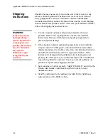
Page 16: ...king materials whenever possible Refer to www golighthouse com rma for detailed instructions Remove attachments and package separately to prevent physical damage 2 If the original container and packin...

Page 17: ...made throughout this section to the EIA TIA 568B standard for Ethernet RJ 45 wiring that must be followed Failure to wire both ends to this standard will cause failure of the instrument and may damag...

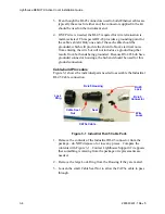
Page 18: ...m both ends being grounded Because RS 485 hub have grounded connector housings the hub end should be used for this ground connection Cable build Procedure Figure 3 1 shows the individual parts needed...

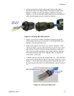
Page 19: ...idual wires 6 Separate the pairs of wires down to the cable s insulation There will be an orange a green a blue and a brown pair of wires Each pair will have a solid color wire and one striped wire of...

Page 20: ...shorter than one eighth inch 3 2 mm Review the photos in Figure 3 4 to ensure accuracy Figure 3 4 EIA TIA 568B Color Code Example Note The pairing of wires in the loom changes at positions 4 through...

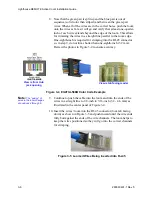
Page 21: ...ds in the RJ 45 to make sure they have been crimped properly Removing the connector at this point is a lot easier than after everything is installed and communication with the instrument is failing du...

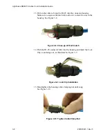
Page 22: ...tch tab to allow it to enter the slot in the housing See Figure 3 8 Figure 3 8 Close up of RJ 45 Latch 14 Push the RJ 45 connector fully into the housing and insert the Lock Clip round edge out as ill...

Page 23: ...retainer ring Verify that its larger opening is facing outward away from the cable as shown in Figure 3 12 Figure 3 12 Cable Connector Completed 18 The hub end of the cable run can now be terminated T...

Page 24: ...and 8 are OFF for MODBUS mode default setting If an address other than 1 is required set DIP SW 1 through 5 to the desired address up to 31 Figure 3 13 DIP Switch Positions 4 Return the cover plate t...

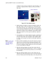
Page 25: ...RAC AC Power Input receptacle and connect to an AC power source Note AC power must be available within 3 feet of the mounting location Figure 3 15 RAC Impactor Assembly Flow Adjust Cover 7 Press and h...

Page 26: ...the highest steady vacuum is achieved then use an automatic center punch to punch two marks one on top piece and other on bottom piece adjacent to each other Note The center punch marks provide align...

Page 27: ...GHT 1 as shown in Figure 3 13 Note Use a tool with a very small pointed tip to change the DIP Switch positions Table 3 1 DIP Switch Setting Definitions Position Description Setting 1 Binary Bit 0 Addr...

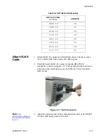
Page 28: ...Switch Addressing DIP SWITCHES 1 2 3 4 5 6 ADDRESS 1 0 0 0 0 0 1 0 1 0 0 0 0 2 1 1 0 0 0 0 3 0 0 1 0 0 0 4 1 0 1 0 0 0 5 0 1 1 0 0 0 6 1 1 1 0 0 0 7 0 0 0 1 0 0 8 1 0 0 1 0 0 9 0 1 0 10 0 10 1 1 0 1 0...

Page 29: ...the lock sleeve at the same time until the key goes into the slot Twist clockwise until it locks Figure 3 17 RJ 45 Connector Note The communication cable can also be connected directly to a PC 3 Attac...

Page 30: ...second delay between the instrument starting or stopping and LMS Express RT changing to a matched state For example if the RAC is started using the Start Stop button on the instrument LMS Express RT m...

Page 31: ...me page under the heading Other Options On the Data Collection page choose Real Time Data Collection See Figure 3 19 Figure 3 19 Data Collection Options Select Add Network Connection in the Connection...

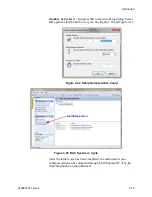
Page 32: ...river dialog box confirm that the Instrument Enable check box is active Select a location for the Instrument Location leave the Instrument Address at 1 and select the LWS Remote Active Count from the...

Page 33: ...o start the RAC on a cycle See Figure 3 22 and Figure 3 23 Figure 3 22 Setup Remote Active Count Figure 3 23 RAC System in Cycle After the initial cycle has been completed the instrument is now config...

Page 34: ...D Note LMS Express RT only measures the estimated volume of sample for the Remote Active Count Begin a sampling cycle by using LMS Express RT or by pressing the Start Stop button The yellow Flow LED a...

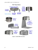
Page 35: ...s with layouts that don t meet standard design criteria 1 The RAC can be installed as a table top unit with a top mount Impactor 2 The RAC can be wall mounted and the Impactor can be slaved to a wall...

Page 36: ...tor Assembly SideMount Assembly with Wall Bracket Impactor Assembly with and Wall Bracket Table top Stand Seal Outlet Fitting P N 211316608 1 Direct Mount Outlet Fitting 211316463 1 Barbed Outlet Fitt...

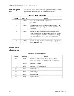
Page 37: ...nds Value Register Action 1 40025 Saves all writable 40025 register values to the Data Record Index Location Number 40026 Saves all writable 40026 register values to instrument Location 0 40029 Set In...

Page 38: ...ment parameters via MODBUS 11 40002 Instrument Start Uses defined Initial Delay Hold Time Sample Interval and counting mode Instrument executes samples and holds until an Instrument Stop command is is...

Page 39: ...d MODBUS Commands See www modbus org for documentation on how to use these commands Table A 1 MODBUS Communications Settings Baud Rate 19200 Data Bits 8 Stop Bits 1 Parity None Hardware Protocol RS485...

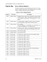
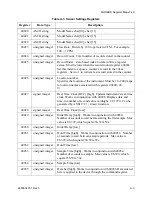
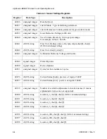
Page 40: ...0 RUNNING bit 1 SAMPLING bit 2 NEW DATA bit 3 DEVICE ERROR bit 12 FLOW STATUS 40004 unsigned integer Firmware version Major version digits are hundreds Minor version digits are tens and ones For exam...

Page 41: ...instrument s real time clock Works in conjunction with 40028 Displays date and time in number of seconds since midnight 1 1 1970 Can be generated by ANSI C C time function 40028 signed integer Real Ti...

Page 42: ...049 signed integer Printer Options 40050 signed integer Device Options 40053 unsigned integer Cycles Set Sets number of cycles 40076 ASCII string Current Status high preview of register 30007 40077 AS...

Page 43: ...nabled Device Options 40050 displays the instrument s device configuration If bit 0 of Register 40050 is set it indicates that the instrument is capable of Fast Download If Bit 1 of Register 40050 is...

Page 44: ...Device Status Bit Description 0 RUNNING Set when a start command is executed remotely via Command 9 manual start or Command 11 instrument start or through the user interface The flag will remained se...

Page 45: ...es not start pump 10 Manual Stop Stops sampling Records counts since Manual Start 11 Instrument Start Automatic Counting Particle Counters Uses defined Initial Delay Hold Time Sample Interval and coun...

Page 46: ...le and analog channels are necessarily active Retrieving data from an inactive channel returns garbage See the Data Enable Registers section of this document for details on how to record data from act...

Page 47: ...teger Particle Channel 1 low 30011 unsigned integer Particle Channel 2 high 30012 unsigned integer Particle Channel 2 low 30013 unsigned integer Particle Channel 3 high 30014 unsigned integer Particle...

Page 48: ...verflow would return a value of 6 in register 30008 bits 1 and 2 are set TRUE Bits 7 to 31 are currently unused Valid Data in Channels 30074 Register 30074 represents the flag bits corresponding to va...

Page 49: ...with the Data Registers For example Data Register 30041 s Data Type register is 41041 Data Types are assigned 4 ASCII characters across 2 registers If a Data Type string contains less than 4 characte...

Page 50: ...nits are stored as 4 character ASCII strings across 2 registers If the Units string contains less than 4 characters or no characters at all the rest of the string is padded with NULLs The table below...

Page 51: ...LE These registers supersede the older Data Enable Registers 31xxx which have been obsoleted m Meters Bar Bar ft 2 Square feet mBar Milli bar m 2 Square meters V Volts ft 3 Cubic feet mV Milli volts m...

Page 52: ...ned int Enable for Particle Channel 2 high 43012 unsigned int Enable for Particle Channel 2 low 43013 unsigned int Enable for Particle Channel 3 high 43014 unsigned int Enable for Particle Channel 3 l...

Page 53: ...are enabled for alarms Use the Threshold registers to set the alarm threshold value This is described in the next section 43045 unsigned int Enable for Analog Channel 3 high 43046 unsigned int Enable...

Page 54: ...es run in parallel with the data registers 30xxx series For example data register 30010 s corresponding threshold register would be 45010 Data register 30016 s threshold register would be 45016 Table...

Page 55: ...Channel 8 high 45024 unsigned int Threshold for Particle Channel 8 low Table A 17 Alarm Threshold Registers set to default value Registers Particle Channel Threshold Value 45009 45010 1 1000 45011 45...

Page 56: ...MODBUS Register Map v1 49 248083401 1 Rev 5 A 18...

Page 57: ...nties and remedies granted under this Section may at LWS s option be terminated C THE FOREGOING WARRANTY IS EXCLUSIVE AND IN LIEU OF ALL OTHER REPRESENTATIONS WARRANTIES AND COVENANTS EXPRESS OR IMPLI...

Page 58: ...Lighthouse REMOTE Active Count Installation Guide B 2 248083401 1 Rev 5...

Page 59: ...7 Device Status Word A 9 Data Type Registers A 10 Data Units Registers A 12 Device Status A 5 Device Status Word A 9 Dimensions 2 2 E Enable Alarming A 15 Enclosure 2 2 Ethernet Cable Plenum Cable 3...

Page 60: ...n to instrument s EEPROM 5 2 Sensor Settings Registers A 2 Setting the Alarm Threshold Value A 17 Setup Instrument Driver 3 18 Shielded Twisted Pair STP cable 3 3 Shipping instructions 3 2 Site Prepar...

Page 61: ...00...

Page 62: ......

Reviews: