RUS
Данный паспорт доступен для скачивания на сайте www.ltcompany.com в разделе «ПРОДУКЦИЯ»
ENG
You are welcome to download the passport in the PRODUCT section on our web-site www.ltcompany.com
KAZ
Бұл төлқұжаты сiз www.ltcompany.com сайтынан, «ӨНІМДЕР» бөлімінен жүктеп аласыз
BLR
Дадзены пашпарт даступны для запампоўкі на сайце www.ltcompany.com ў раздзеле «ПРАДУКЦЫЯ»
UKR
Электронна версія паспорту доступна на сайті www.ltcompany.com в розділі «ПРОДУКЦІЯ»
4
5. Codes for installation
5.1. Operation of the floodlight
is made in accordance with the “Rules of technical operation of consumers’ electrical units”.
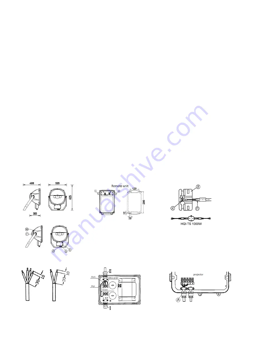
5.2. Unpack the floodlight (Fig. 1) and the remote unit (Fig. 2).
5.3. Install the remote unit and the floodlight by fixing the harp of the floodlight on the supporting surface with M12 screws (M16 screws for floodlights with capacity of 2 kW), put tab washers
under the screw heads (torque is 80 N/m (100 N/m for floodlights with capacity of 2 kW)). The distance between the floodlight and the illuminated surface shall not be less than 3 m (see Fig. 7).
See the operating position for floodlights with the symmetrical and round-symmetrical reflector in Fig. 7a, for floodlights with the asymmetrical reflector
– in Fig. 7b.
5.4.Installation and replacement of the lamp (Fig. 3):
5.4.1. Open the back cover of the floodlight by uncliping 2 “M” steel clips
5.4.2. Insert the lamp into the spring “П” of the lamp holder “Л”. The sealed ledge of the lamp shall be directed towards the floodlight glass.
5.4.3. Install the terminals
of the lamp into the terminals of the lamp holder “K”, fix them with nuts, and put washers under them (torque is 2.5 N/m). Ensure that the burner of the lamp is in the
center of the reflector.
5.4.4. Close the rear cover and fix it with clips. Check that the gasket is properly positioned in the casing.
5.5. Electrical connection of the floodlight with the remote unit that contains ballasts:
Attention: Connection of the floodlight to AC is only possible through the remote unit that contains ballasts (vendor supplied).
5.5.1. Open the cover of the remote unit.
5.5.2. Insert a 4-wire cable into the remote unit through the sealed insulator II (3-wire cable through the sealed insulator II
– for floodlights with capacity of 2 kW) (9-12 mm diameter) (user
supplied). Wires shall be preliminarily rubbed down, as shown in Fig. 4. Pass the cable under the cable clamp and connect the conductors to the terminal block, as shown in Fig. 5.
5.5.3. Open the cover of the floodlight connection unit “C” (Fig. 1).
5.5.4. Insert a 4-wire cable into the floodlight
through ‘”A” sealed insulator (3-wire cable – for floodlights with capacity of 2 kW) (user supplied) that runs from the seal insulator II of the remote
unit. Pass the cable under the cable clamp (rubbing down the wire as shown in Fig. 4).
5.5.5. Connect the conductors to the terminal block (Fig. 6)
5.5.6. Fix the cables by tightening the cable clamps.
5.6. Close the covers of the floodlight connection unit and the remote unit. Ensure the correct position of the sealant.
5.7. Tighten cap nuts of the cable gland.
5.8. Set the floodlight at the required angle to the vertical line using the angular scale “Г” (Fig. 1).
5.9. Clean the protection glass with a soft cloth dampened in a mild soap solution.
5.10. Replace the protective glass cracked or otherwise damaged.
5.11. After installing the floodlight in the operating position, tighten fixing bolts on both sides of the fixing harp (bracket) against the stop.
5.12. It is allowed to move the electronic control gear unit from the floodlight at a distance of 50-70 m.
Pic.1
Pic.2
Pic.3
Pic.4
Pic.5
Pic.6


