background image

12


LIGHTMEN™

2.7 DMX CONTROL : 10-CHANNEL MODE

Summary of Contents for Apollo

Page 1: ......

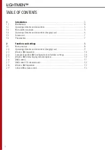
Page 2: ...metrics 2 Functions and settings 2 1 Menu structure 2 2 Operating elements and connections charging case 2 3 Wireless DMX operation 2 4 Example of possible DMX configurations and address settings 2 5 Wireless DMX status display code descriptions 2 6 DMX control 2 7 DMX control 10 channel mode 2 8 Wireless DMX operation 2 9 Infrared IR6 remote control 3 4 5 5 6 7 7 8 8 9 10 10 10 11 12 13 13 LIGHTM...

Page 3: ...ooling Charging station in rugged touring case holds 6 units Password protected key lock Black finish Threaded receiver for clamp mounting DMX Manual Standalone Auto Shows Master Slave IR control SPECIFICATIONS Light Source Beam Angle Field Angle Output Color Mixing Strobe Dimming Control DMX Channels Display Mains Consumption Power connections Battery Housing Finish IP rating Cooling Max Amblent ...

Page 4: ...le condition and should be replaced immediately even when a small problem is detected It is recommended to clean the front at regular intervals from impurities caused by dust smoke or other particles to ensure that the light is radiated at maximum brightness For cleaning disconnect the main plug from the socket Use a soft clean cloth moistened with a mild detergent Then carefully wipe the part dry...

Page 5: ...5 LIGHTMEN 1 2 OPERATING ELEMENTS AND CONNECTIONS 1 3 MENU BUTTON OVERVIEW ...

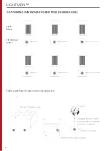
Page 6: ...6 LIGHTMEN 1 4 OPERATING ELEMENTS AND CONNECTIONS CHARGING CASE apollo Fixture Charging case contact Flight case with PowerCon power in and six charging stations ...

Page 7: ...GBW Projection Distance m full 0 1m 18580 3m 2064 5m 743 7m 379 10m 186 1 7 PHOTOMETRICS Lumens 1162 1 3 5 7 R W G B distance m color 10 RGBW lux 4422 491 177 90 44 9823 1091 393 200 98 1541 171 62 31 15 12188 1354 488 249 122 18580 2064 743 379 186 Lumens 335 572 113 705 1162 ...

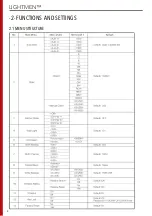
Page 8: ...8 LIGHTMEN 2 1 MENU STRUCTURE 2 FUNCTIONS AND SETTINGS ...

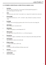
Page 9: ...ther 10 20 or 30 seconds or choose always ON 5 Information Fixture software version and runtime clock 6 DMX Address Set DMX starting address at a value between 001 512 7 DMX Channel Select DMX mode 3 channel HSV or HSI or 4 6 or 10 channel operation 8 Master Slave Assign fixture to operate as either Master or Slave unit in configurations with multiple apollo fixtures 9 White Balance Adjust RGB lev...

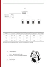
Page 10: ...10 LIGHTMEN 2 3 WIRELESS DMX OPERATION 2 4 EXAMPLE OF POSSIBLE DMX CONFIGURATIONS AND ADDRESS SET 2 5 WIRELESS DMX STATUS DISPLAY CODE DESCRIPTIONS ...

Page 11: ...NGS 11 LIGHTMEN 2 6 DMX CONTROL 4 Channel mode 6 Channel mode 3 Channel hsv mode 3 Channel hsi mode ...

Page 12: ...12 LIGHTMEN 2 7 DMX CONTROL 10 CHANNEL MODE ...

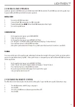
Page 13: ...cator will change to a symbol above the bars while connection is establish PAIRING Once successfully paired the apollo signal indicator will indicate the strength of the signal At this point the apollo is ready to be operated wirelessly by DMX If the apollo fixture is subsequently used with a different W DMX transmitter follow steps below 1 On the apollo control panel go to WIRELESS SETTING 2 Sele...

Page 14: ...tween 0 9 to choose colors Corresponding to white full output red orange yellow green purple blue magenta pink amber Press MANUAL then Press R G B or W buttons Increase decrease output of each color using buttons Adjusts total output level Increase decrease output level Enable adjustment of strobe rate Increase decrease strobe rate Press again to turn off strobe Turn off all output Press again to ...

Page 15: ...15 LIGHTMEN NOTES ...

Page 16: ...Address Stureparksvägen 7 Phone 0522 440 880 45155 Uddevalla Email sales interlite se Sweden Web www interlite se Contact Information ...

Reviews: