background image

×

×

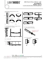
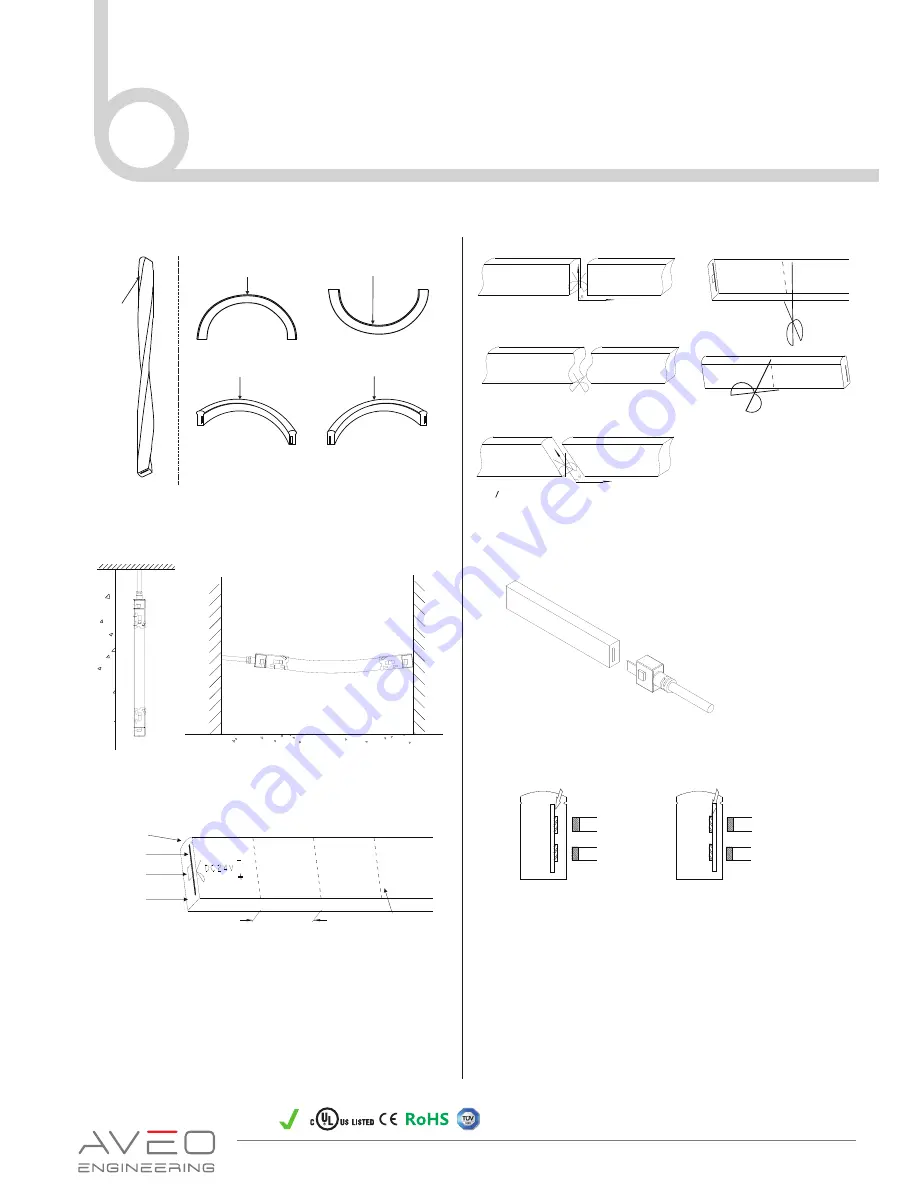
Fig

.

5


Unit


cutting


guide


(

Only applicable to DIY 

accessories

)

Pay attention to”+” both

on light body and front 

connector

Light Surface

Light Surface

×

×

Light Surface

×

Fig

.

2


Fig

.

3


 Recommened Use

Light Surface

Light Surface

Light Surface

PCB

LED

PVC

83.3mm

Cutting


line

×

×

The correct cutting way,

R

=

90

°

Wave cutting is incorrect

R=90

°

is incorrect

×

Connector Pins

×

Connector Pins

×

Connector Pins

Connector Pins

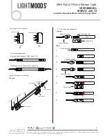
For 01 Type Front Connector

MINI Flat LED Neon Ribbon Light

USER MANUAL

MNFLSC-24V-72

(Green/Blue/Warm White/White/Cool White/Daylight White)

Palm Coast, Florida, USA / Los Angeles, California, USA /  Pribram, Czech Republic / Birmingham, U.K. / Kuala Lumpur, Malaysia / Mumbai, India
Email: christian@aveoengineering.com / Web: www.aveoengineering.com

DO-160G

tested

2

Twisting the light is forbidden and observe to correct 

bending orientation

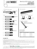
Fig. 4 Installation of the light hanging suspended in the air as 

           the picture illustrates is forbidden. 

Fig.6 Correct insertion of connector pins

Light

Moods

TM

Summary of Contents for MNFLSC-24V-72

Page 1: ...ELY ASSEMBLY AND INSTALLATION FIGURES WARNING 1 Before making any cuts installation maintenance or connection be sure the mains is disconnected 2 NOTE ALL CONNECTOR JOINTS MUST BE CONNECTED CORRECTLY TO ACHIEVE IP68 RATING 3 Please operate this flex light according to the instructions and confirm the work voltage it must be matched with product requirements 4 Please confirm the polarity of connect...

Page 2: ...ctor Pins For 01 Type Front Connector MINI Flat LED Neon Ribbon Light USER MANUAL MNFLSC 24V 72 Green Blue Warm White White Cool White Daylight White Palm Coast Florida USA Los Angeles California USA Pribram Czech Republic Birmingham U K Kuala Lumpur Malaysia Mumbai India Email christian aveoengineering com Web www aveoengineering com DO 160G tested 2 Twisting the light is forbidden and observe to...

Page 3: ... for Max length 15m Double ends connection for Max length 30m Fig 8 DIY Connector Assemble Diagram For 02 Type Front Connector Connector Pins Connector Pins Front Connector U Steel Plate U Steel Plate Anti skidding Clip Rubber G asket The Tail Plug Light Anti skidding Clip Rubber Gasket Front Connector Assemble Front Connector Rubber Gasket U Steel Plate Anti skidding Clip Light Step 1 2 3 4 5 6 7...

Page 4: ...y we reserve the right to charge for time and parts Advances technology for the will be selected firstly 2 Warranty excludes below Any man made damages caused from improper operation assembly wiring connection installation transport and storage Improper input voltage current operating and working environment The product appears to have excessive physical damage Damage due to natural disasters and ...

Reviews: