631 Airport Road, Fall River, MA 02720 • (508) 679-8131 • Fax (508) 674-4710
We reserve the right to change details of design, materials and finish.
www.lightolier.com © 2010 Philips Group •
Lighting Systems
IS_CL
Page 1 of 2
Instruction Sheet for Assembly and Installation of Covelite
C1010 ~
59.31233.00
• READ AND UNDERSTAND THESE INSTRUCTIONS BEFORE INSTALLING THE PRODUCT.
• KEEP THESE INSTRUCTIONS FOR MAINTENANCE REFERENCE.
• THIS FIXTURE IS INTENDED TO BE INSTALLED IN ACCORDANCE WITH THE NATIONAL ELECTRIC CODE AND LOCAL REGULATIONS.
• TO ASSURE FULL COMPLIANCE WITH LOCAL CODES AND REGULATIONS, CHECK WITH THE LOCAL ELECTRICAL INSPECTOR
BEFORE INSTALLATION.
• TO PREVENT ELECTRICAL SHOCK, TURN OFF ELECTRICITY AT ELECTRICAL PANEL BEFORE PROCEEDING.
• DO NOT INSTALL THIS SYSTEM IN A WET OR DAMP LOCATION.
• DO NOT ENERGIZE ANYTHING OTHER THAN THE FIXTURES IN THE SYSTEM.
• CONTRACTOR IS RESPONSIBLE FOR ADEQUATELY REINFORCING THE MOUNTING LOCATIONS OF THIS FIXTURE.
These instructions review how to install CoveLite fixtures. CoveLite can be installed as individual units or connected together to create
continuous runs. If the units are mounted in a radial pattern there must be protection for exposed conductors and at connections.
MATERIALS REQUIRED
• Mounting screws appropriate for the mounting surface
• Appropriate screwdriver(s)
• One 1/2” (for 7/8” hole) knock-out seal for each end of row
• Wire nuts
• Flexible conduit connector for each power connection
• Flexible conduit required for corners and if fixture is mounted in a radial pattern.
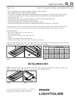
The fixtures come in different lengths and can be mounted to a horizontal or vertical surface in two different positions. Figure 1 depicts the
different mounting positions and Figure 2 shows the actual length for nominal fixture lengths.
Nominal
Fixture
Length
Actual Fixture Length
1 Light T5
2 Light T5
1 Light T8 2 Light T8
2'
1'-11"
1'-11"
2'
2'
3'
2'-10 1/2"
2'-10 1/2"
3'
3'
4'
3'-10 1/2"
3'-10 1/2"
4'
4'
6'
5'-9"
5'-9"
6'
6'
8'
7'-9"
7'-9"
8'
8'
Horizontal Mounting, Position A
Vertical Mounting, Position A
Figure 2
Figure 1
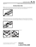
Figure 3A
Figure 3B
STEP 1:
Determine the correct mounting position and mount the first fixture using appropriate fasteners through the slots in the housing
(Figure 3A). For 2 light T8 fixtures the screw is hole is located on the end of the fixture (Figure 3B).
A
H izontal
u ting Pos t on A
Vert cal Mounting, Posi on A
A
B
B
C
INSTALLATIoN STepS


