Page
2
of
5
AS-42D COMPACT DMX DIMMER
Version 2.0
OWNERS
MANUAL
02/14/2005
www.lightronics.com
Lightronics Inc.
509 Central Drive, Virginia Beach, VA 23454
Tel: 757 486 3588
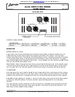
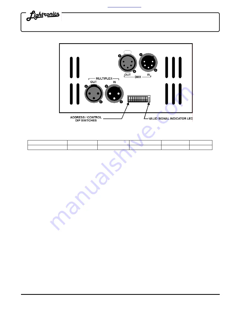
AS-42D END VIEW
CONTROL SIGNAL WIRING:
Connector Pin #
1
2
3
4
5
LMX-128 (multiplex) LMX Common
Console Power
Multiplex Signal
Not Used
Not Used
DMX-512
DMX Common DMX Data -
DMX Data +
Not Used
Not Used
OPERATION
NORMAL MODE (non-chaser)
A green LED in the end panel will indicate that a valid control signal (DMX or multiplex) is applied to the unit.
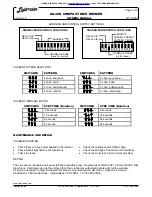
A DIP switch block on the end panel selects the starting channel number of the dimmer. The 7 right hand
switches control this function. For example, if all switch positions are down - the dimmer will respond to channels
1-4. Moving the switch position on the far right up will set the dimmer to respond to channels 5-8. A complete
table of channel assignments is provided in this manual.. You can address up to 512 channels using DMX control
and up to 128 channels with multiplex control.
RELAY MODE: Pairs of channels (1/2 and/or 3/4) may be switched into the relay mode. In this mode the output
of these channels will be either off or full on depending on the control console channel setting. The trip point for
turn on is aprox. 50%. The 2 left hand switches on the DIP switch block control relay mode channel selection.
CHASER MODE:
When operating in the chaser mode the AS-42D becomes independent of the control console and other dimmers.
The green LED indicator is OUT when in the chaser mode. Chaser mode is turned on and off by one of the DIP
switches on the end of the unit. A diagram on the unit cover unit shows the switch settings for chaser operation.
Eight different chaser patterns are available. A “bounce” condition may be used on several of the chase patterns
by setting one of the DIP switches. The bounce condition causes the chase pattern to run in alternating
directions.
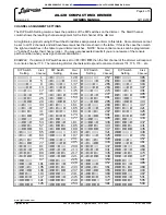
The chase step time may be controlled for up to 64 seconds per step. Step fade time is proportional to the step
time. If a channel is in the relay mode during chaser operation - it will “snap” on and off (zero fade time). The
tables below show the details of chaser settings.
ORDER DIRECTLY TODAY AT:
www.BulbAmerica.com
or CALL TOLL FREE 888-505-2111


