1. Introduction
DVIDL-OPT series – User's Manual
6
1.4. Features of the Extenders
1.5.
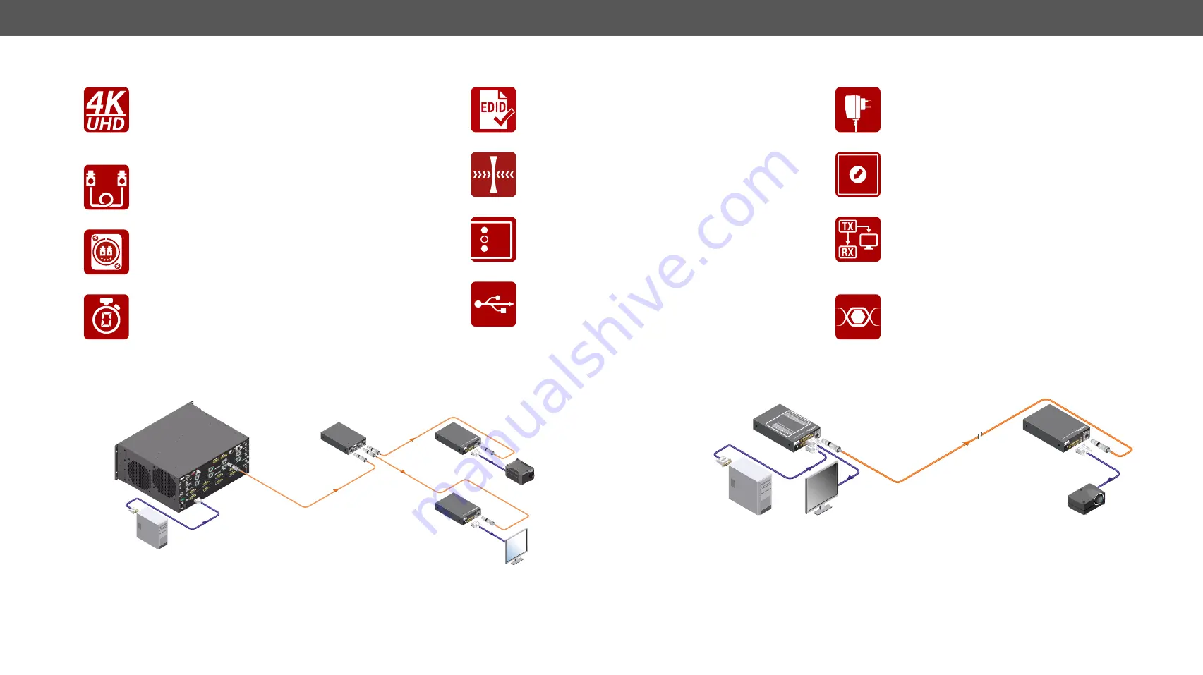
Typical Applications
LC
50/1
25 M
ULT
IMOD
E
LAS
ER
ACTIV
E
L.ACT
IVE
L.ACT
IVE
L.ACT
IVE
L.ACT
IVE
L.ACT
IVE
L.ACT
IVE
L. A
.
OUT
1A
OU
T 1B
OUT
2A
OU
T 2B
OUT
3A
OU
T 3B
OUT
4A
OU
T 4B
LC
50/1
25 M
ULT
IMOD
E
LAS
ER
ACTIV
E
L.ACT
IVE
L.ACT
IVE
L.ACT
IVE
L.ACT
IVE
L.ACT
IVE
L.ACT
IVE
L. A
.
OUT
1A
OU
T 1B
OUT
2A
OU
T 2B
OUT
3A
OUT
3B
OUT
4A
OU
T 4B
4 C
H D
UAL
LIN
K D
VI IN
PUT
BO
ARD
MX-D
VID
L-IB
4 C
H D
UAL
LIN
K D
VI IN
PUT
BO
ARD
MX-D
VID
L-IB
PIN:
2.35mm
5V 1.
5A DC
OUT
PUT
FIBER
INPUT
Fiber
INPUT
A:
CLK:
TMDS
3,4,
5 (L
ink
2)
Fiber
INPUT
B:
CLK:
TMDS
0,1,
2 (L
ink
1)
Mad
e in
For single link DVI signal use Fiber link 1 only
.
For dual link DVI extension use both Link 1 and Link 2.
Link 1: Fiber output
A
Fiber Input B
Link 2: Fiber output B Fiber input
A
DVIDL-OPT
-RX100
PIN:
2.35mm
5V 1.
5A DC
OUT
PUT
FIBER
INPUT
Fiber
INPUT
A:
CLK:
TMDS
3,4,
5 (L
ink
2)
Fiber
INPUT
B:
CLK:
TMDS
0,1,
2 (L
ink
1)
Mad
e in
For single link DVI signal use Fiber link 1 only
.
For dual link DVI extension use both Li
nk 1 and Link
2.
Link 1: Fiber output
A Fiber Input B
Link 2: Fiber output B
Fibe
r inp
ut A
DVIDL-OPT
-RX100
OUT
PUT
2
-4dB
loss
OUT
PUT
2
-4dB
loss
INP
UT OUT
PUT
INPUT
Neutrik OpticalCON
Duo hybrid
Neutrik OpticalCON
Duo hybrid
Neutrik OpticalCON
Duo hybrid
DVIDL-OPT-RX100
DVIDL-OPT-RX100
Dual-Link
Projector
Dual-Link
Monitor
Dual-Link
DVI
Dual-Link
DVI
Dual-Link PC
MX-FR17
SP2OPT-NT
MX-DVIDL-OPT-OB-NT
MX-DVIDL-OPT-OB-NT
MX-DVIDL-IB
MX-DVIDL-IB
Integrated System Diagram
PIN:
2.35mm
5V 1.
5A DC
OUTP
UT
FIBE
R INP
UT
Made
in
DVIDL-OPT
-TX200
Uni
versal EDID Detailed T
imings
192
0X1200P@60
2048X1080P@60
192
0X1080P@60
EDID ST
ATUS F
UNCTIO
NS
RED:
INV
ALID EDID MEMOR
Y
GREEN:
VALID EDID SELECTED
For
single link DVI
signal
use
Fiber li
nk 1
only
.
For
dual
link DVI
extension
use
both Link 1 and Link 2.
Link 1: Fiber output
A
Fiber input B
Link 2: Fiber output B
Fiber input
A
Fiber OUTPUT
A: CLK; TMDS 0,
1,2 (Link 1)
Fiber OUTPUT B: CLK; TMDS 3,4,5
(Link 2)
PIN:
2.35mm
5V 1.
5A DC
OUTP
UT
FIBE
R IN
PUT
Fiber
INP
UT
A: CLK:
TMDS
3,4,
5 (Li
nk 2)
Fiber
INP
UT
B: CL
K: TM
DS
0,1,
2 (L
ink
1)
Made
in
For single link DVI signal use
Fiber link 1 only
.
For dual link DVI extension use both Link 1 and Link 2.
Link 1: Fiber output
A Fiber Input B
Link 2: Fiber output B Fiber input
A
DVIDL-OPT
-RX100
Neutrik OpticalCON
Duo hybrid up to 2500m
DVIDL-OPT-TX200
DVIDL-OPT-RX100
Dual-Link PC
Local Monitor
Dual-Link Projector
Dual-Link
DVI
Dual-Link
DVI
Dual-Link
DVI
Standalone Application Diagram
Supports 4K Resolutions
Transmitting Dual-Link video signals up to 4096x2400
resolution, including all standard HDTV resolutions.
Unencrypted signals up to 330 MHz pixel clock
frequency (up to 165 MHz TMDS clock frequency).
Single-Link Operation Mode with One Fiber
When Single-Link DVI signal is transmitted, all of the
high-speed TMDS data lanes are transmitted using
only one multimode 50/125 fiber optical cable.
Neutrik OpticalCON Fiber Connector
Neutrik NO2-4FDW type LC-Duplex connector,
eliminates its inherent weakness, guaranteeing a safe,
dust protected, and durable connection.
Zero Frame Delay
DVIDL-OPT-TX200 add no frame noticeable delay to the
switched signal. There is no frame or line period delays
to the signals when passing a Lightware router.
Advanced EDID Management
The user can emulate any EDID on the inputs
independently, read out and store any attached
monitor's EDID in 100 internal memory locations.
Galvanic Isolation between Source and Display
Lightware fiber optical extenders are isolated between
transmitter and receiver to eliminate ground loop noise
or HUM effects.
LED1
LED2
LED3
Front Panel LEDs
Source-, signal-, monitor- and laser detection, to get
immediate feedback about the status of connected
devices.
USB Control
Input/output status, EDID Management, and hardware
information can be accessed with Lightware Device
Controller software via USB connection. Firmware
upgrade can also be performed over this interface.
Locking DC Connector
Special locking plug of wall adaptor ensures safe power
supply. This type of connector prevents accidental
disconnections.
01
2
3
4 5 6 7
8
9
Front Panel Control (Transmitter)
EDID address selection with two decimal rotary
switches and LEARN button are available for Advanced
EDID Management.
Local Monitor Output (Transmitter)
The user can attach a local monitor to observe the
video signal sent through the fiber optical cable. The
resolution and clock frequency are the same on DVI
and fiber optical connectors.
TMDS Reclocking (Receiver)
Removes jitter caused by long cables; the output has
a clean, jitter free signal, eliminating signal instability
and distortion caused by long cables or connector
reflections.


