ISG Allegro LightWise USB 3.0 Technical Manual Version 1.3.1
31
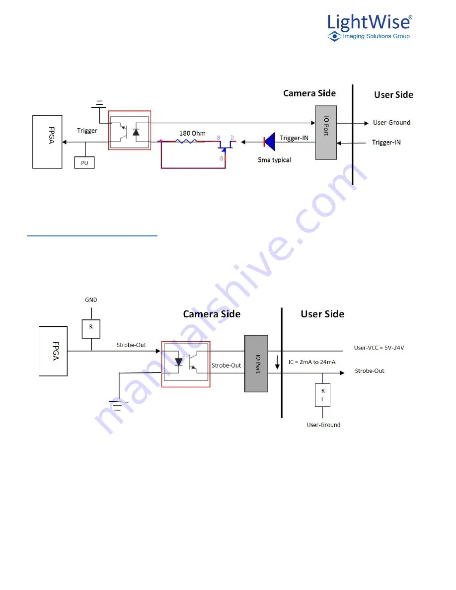
The drawing below shows the camera’s Trigger Interface circuit.
`
Camera Strobe Details
Strobe1-2 outputs: The camera provides two optically isolated Strobe outputs (npn transistor). The output
modes (level high or level low and pulse duration) are programmable.
The following diagram shows the interface circuit for each of the Strobe outputs.
Note: the amount of current flow, IC, is the function of User-resistor- Load and User-VCC. It is recommended the IC be kept at 2ma
to 24ma range when Saturation voltage, VCE, is at 0.5V max
.
Summary of Contents for ISG Allegro
Page 1: ...Technical Manual ISG LightWise Allegro USB3 Vision Cameras Version 1 3 1 Last Revision 3 31 15...
Page 16: ...ISG Allegro LightWise USB 3 0 Technical Manual Version 1 3 1 16 Select Next Select Next...
Page 52: ...ISG Allegro LightWise USB 3 0 Technical Manual Version 1 3 1 52 11 Trouble Shooting...


