Technical Description &
Configuration Guide
Performance
and Alarm Management
LigoWave
Page 65
Command
Description
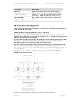
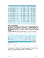
Alarm cfg
<
groupID>[<global><led>
<aux><log><snmp>]
Allows defining detailed alarm representation settings.
[<global> <led> <aux> <log> <snmp>] must be defined in
a row of „1‟s or „0‟s of 5 values for specified group ID with
<group ID>. „1‟ means the values are „on‟ and „0‟ – „off‟.
Alarm threshold
{stat}|{<Alarm
ID>lo|hi|delta <value>}
Sets threshold values outside which alarm status will be
shown.
Performance Management
The main aim of the
performance management
is to register mostly critical device performance event
values in predefined time intervals.
Performance Management Data Collection
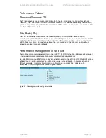
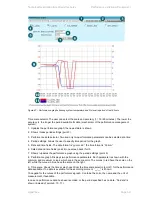
The performance parameters are collected within time intervals of 1 min., 15 min. and 1 hour. List
reserved space for every time interval is 1440 records (see
Figure 43
– Functional architecture for data
collection, history and thresholding treatment
).
Second-by-second the input performance event values are stored by updating previous second values.
The register is called
current register
. The
current register
contains the performance values
collected second-by-second from the reset instant to the present second.
At the end of period the contents of current registers are transferred to the history registers (records),
with a time-date stamp to identify the period, after which the current register must be reset.
Some current register values are passed to the threshold crossing control unit for triggering threshold
crossing notification.
Optionally, the same values are output to the Message Communication Function (MCF) to be
forwarded to the managing system.
Figure 43
– Functional architecture for data collection, history and thresholding treatment


