background image

This manual is designed to make it as easy as possible for you to assemble, install, operate and maintain

the ceiling fan. The following tools listed are required for assembly and installation:

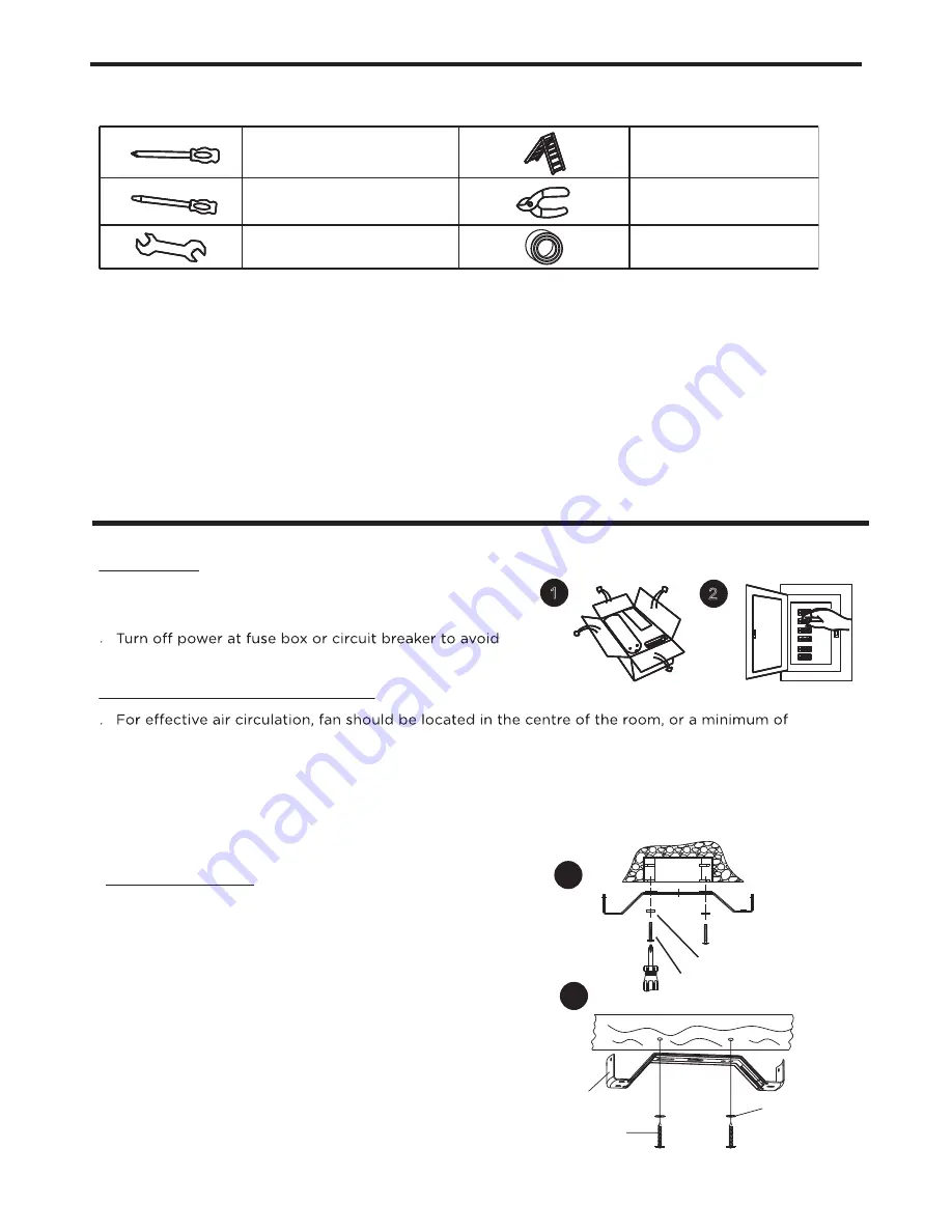
TOOLS REQUIRED FOR ASSEMBLY

1x star-head screwdriver

1x flat screwdriver

1x wrench

1x stepladder

1x wire stripper/pliers

1x electrical tape

After opening the package you should find all the necessary parts for installing this ceiling fan.

The box should also contain:
5 fan blades
5 decorative fan blade brackets
1 motor with decorative housing
1 light kit with complete installation hardware
3 glass shades
1 mounting bracket with complete installation

1   “J” hook

1   zip tie

Parts Pack Containing:
2 wood screws with flat washers
2 mounting screws with lock washers 
1 extra light kit screw
1 extra blade bracket screw
3 wire connectors
16 blade screws, flat washers and hexagon nuts
2 pull chains with fobs

ASSEMBLY

1

2

Preparing for installation

Getting ready

.   Unpack and inspect carefully to make sure all parts are

    included and not damaged (see Fig. 1). Lay all pieces out

    on a working space.

    possible electrical shock (see Fig. 2).

.   Choose a location where there is a high enough ceiling clearance (at least 8’ 3” (2.5 m) from the
    floor to the ceiling fan’s lowest moving part).
.   Ensure that the outlet box in the room’s ceiling can support the weight of the fan. Typically, if the
    outlet box is marked acceptable for fan support, it can hold the fan securely.

Choosing a location for the ceiling fan

32” (81.3 cm) from adjacent walls or obstructions. 

Installation

1. Mounting bracket

3

.   

.     

Securely attach the mounting bracket to
an outlet box marked “

Acceptable for Fan

Support

”, using the supplied outlet box 

screws with lock washers (see Fig. 3a).

.  

  Remove the four sets of side screws from 

  mounting bracket and save for future use.


Normal masonry ceiling

Wooden ceiling

Drill two mounting holes in the ceiling 

joist.Securely attach the mounting 

bracket to the wooden ceiling as 

indicated below (fig. 3b). 

3a

3b


Outlet box screw 

Lock washer

Mounting 

 bracket


Flat

washer 

wood screw

Summary of Contents for 052-4328-4

Page 1: ...42 Hugger Ceiling FAN OWNER S MANUAL 052 4328 4 Caution For your safety please read and understand this manual before installing or operating this product 052 4329 2 V 1 2016 Toll free 1 866 788 7389...

Page 2: ...ew 1 Important safety instructions 2 Rules for safe installation 2 Tools required for assembly 3 Assembly 3 Operation 7 Maintenance 8 Care and cleaning 8 Troubleshooting 8 Environmental protection 9 W...

Page 3: ...K Hugger Housing Mounting Bracket Motor Support Bar Motor Fan Pull Chain Switch Housing Light Kit Light Pull Chain Blade Arm Glass Shade 1 1 1 1 1 1 1 1 5 3 Blade 5 EXPLODED VIEW 1 A B C D E F G H I J...

Page 4: ...from improper use or noncompliance with the instructions CAUTION To avoid possible electric shock be sure electricity at the fuse box or the circuit breaker All wiring must be done in accordance with...

Page 5: ...for installation Getting ready Unpack and inspect carefully to make sure all parts are included and not damaged see Fig 1 Lay all pieces out on a working space possible electrical shock see Fig 2 Cho...

Page 6: ...opper or green Live wire typically black Neutral wire white ASSEMBLY L WARNING before wiring Screw wire connectors 3 are provided onto the tops of the twisted wires see Fig 5a Fasten them with electri...

Page 7: ...ws and washers from the mounting bracket see Fig 8 Housing screw Mounting bracket Housing screw Motor Motor housing Slide motor housing over motor assembly Secure to the sides of mounting bracket with...

Page 8: ...it Place the neck of glass into light housing cup Insert and tighten the glass screws see Fig 15 6 Remove the screws on the bottom of the motor and use them to attach the blade assembly to the motor E...

Page 9: ...on the fan at medium speed 3 Turn on the fan at low speed The light pull chain controls the status of light 1 Turn on the light Forward and reverse direction function This ceiling fan is equipped wit...

Page 10: ...le reason Blade screws are loose The mounting bracket or canopy is loose Screws securing decorative housing to hanger are loose Lamp shades or bulbs are loose Screws securing downrod to hanger are loo...

Page 11: ...e eraser end of a pencil to change the forward reverse slide switch Place fan in the centre of the room so there is at least 12 30 cm between the end of the blades and walls or other obstructions Make...

Page 12: ...fuel lubricants vacuum bags blades belts sandpaper bits fluids tune ups or adjustments e This warranty will not apply where damage is caused by repairs made or attempted by others i e persons not aut...

Reviews: