background image

CD65


 Certified

Operation and Service Manual

Lily Corporation

240  South  Broadway

Aurora,  Illinois      60505 - 4205

United  States  of  America

Phone:

(01) 630 - 892 - 0860

Fax:

(01) 630 - 892 - 5623

Email:  postoffice@lilycorp.com

Web Site:  www.lilycorp.com

© 2000 Lily Corporation

Product Warranty and Disclaimer.................... . 2
Safety Precautions ................................................. 2

THE RESIN SUPPLY

The Options.......................................................3

      The Connections ................................................... 3

THE AIR SUPPLY

Connections & Requirements ............................ 4

OPERATION

To Begin With ........................................................ 5
Dispensing .............................................................. 5
Shot sizing .............................................................. 6
Remote Trigger Assembly .................................. 7
Shut Down .............................................................. 8
Clean-up ................................................................. 8
Ratio Assurance Check .................................... 1 0
Changing Ratio .................................................... 11

THE SYSTEM, AND HOW IT WORKS

The Fluid Circuit ................................................ 1 2
Coco Valve Module ........................................... 1 3
The Fill Sensors ................................................. 1 3
The  Pneumatic Control Circuit ....................... 1 3

SERVICE

Lubrication .......................................................... 1 4
Coco Module ...................................................... 1 4
Metering Cylinders ........................................... 1 8
Trouble Shooting ................................................ 2 0

APPENDIX -  ASSEMBLY IDENTIFICATION

Serial Number

Summary of Contents for CD65

Page 1: ...cautions 2 THE RESIN SUPPLY The Options 3 The Connections 3 THE AIR SUPPLY Connections Requirements 4 OPERATION To Begin With 5 Dispensing 5 Shot sizing 6 Remote Trigger Assembly 7 Shut Down 8 Clean u...

Page 2: ...D SAFETY PRECAUTIONS The CD65 can develop fluid pressures in excess of 2 000 pounds per square inch psi Everyone within 25 feet should wear eye protection when the system is energized Mechanical membe...

Page 3: ...m before dispensing Stowthecapsonthemagneticflangeofthechannel Leavetheinletfluidfittingsconnected Theirdisconnectionandre connection riskscostlymis connection The CD65 fluid valves are rated at 3 500...

Page 4: ...y and replacethemwhendirty Do not allow the air compressor to overheat Carbon deposits due to overheated compressor oils will interfere with thefunctionofthecontrolvalves Donotallowanyadditivestoenter...

Page 5: ...orairleaks Thispracticewillidentifyanydamagedtubing seals or fittingsbeforethesystemismovedonsite Following the high pressure check reduce the pressure to that selected for the application at hand The...

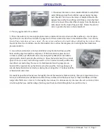
Page 6: ...ack steps must be taken to avoid entrapping air beneath thematerialpiston orallowingittoaccumulate Aircaneasilybeentrappedwithinathickmaterialifitisnothandledcarefullywhentransferringitfromoneonecon t...

Page 7: ...for cleaning Use and care The TSO and SSO valves retain the dispense pressure within the hoses during refill cycles and after the dispenser is switched off as well For safe disconnec tion of the hoses...

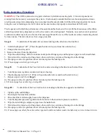
Page 8: ...be taken at shut down if a a low viscosity resin is being used and b amixerormanifoldis fixed directly to the outlet fittings of the Coco module The proce dureiscalled burping Burping is necessary bec...

Page 9: ...an the mixer and tubing However if a thick material must be purged more bursts will be required Keep the bursts as small as possible for large dosages of solventchoketheairstreamvelocity reducingthesc...

Page 10: ...s again and then place a paper towel beneath them 5 Waitatleastfiveminutes andthenobservethetowelforanyevidenceofleakagefromthefittings 6a If seepage occurred regardless of how minute replace the leak...

Page 11: ...linderendcap Thematerialinthemetering cylinderwillbeforcedtoflowbackthroughtheinletfitting Positiona container to catch this material If the piston does not go down easily use a strap wrench to free i...

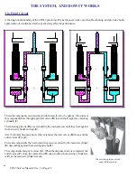
Page 12: ...components then exit under the pressure exerted by the main air cylinder E descendingagainstthemeteringpistons D Thecomponentsmergeatamixer G Whenthedispensestrokeiscompleted the outlet valves F close...

Page 13: ...ingthemeteringcylinderstorefill Notethatitisimpossiblefortheinletoroutlet valvestoopenuntilaftertheoppositevalvesareclosed COCOcannotmakeamistake The Fill Sensors Sensorspreventthedispensecycleuntilbo...

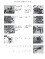
Page 14: ...easily replaced in the course of ball seal replacement When servicing the coco module refer to the exploded parts view on page 30 as well as the illustrated steps below Disassembly Turn the dispenser...

Page 15: ...alve to the spacer block If they do not separate easily tap them apart Use a plastic mallet 5 Grasp the coupler shaft M 581 with a cushioned tool and gently work it and its bushing M 802 from the cavi...

Page 16: ...or seal S 332 with the spring groove facing away from the ball 7 Install the flat washer over the seal and apply silicone lube to hold it in place Install the spring concave side to the ball 8 Press a...

Page 17: ...e disassembly the inlet valves the bottom valves should be open and the upper outlet valves closed If for some reason the unit is reassembled with the rod retracted the valve orientation should be the...

Page 18: ...oughly Examine the cylinder If it is scratched or other wise damaged it must be replaced The Metering Cylinders 1 Grasp the metering piston and press it into itscylinder thuspurging the component bac...

Page 19: ...ad end first intothebottom threaded end of the meteringcylinder 11 Use the seal pick P 457 to remove the base manifold o ring seal Clean the pocket thoroughly before installing a new seal 12 Apply an...

Page 20: ...ect the material inlet hose at the dispenser and check the flow If the flow is restricted check for an obstruction in the material supply line or insufficient delivery from the pressure vessel or tran...

Page 21: ...P 336 Coco module is sluggish stalls or binds Material contains too much abrasive Change materials Low air supply pressure Misalignment in assembly of valve bodies See step 16 on Page 17 Main air cyl...

Page 22: ...pletes its descent or The Stop switch on the RTA is pressed Signals from the Shot Size switch the on off switch and the main air cylinder all pass through the OR element From there the signal travels...

Page 23: ...CD65 Service Manual Ver 1 2 Page 23 APPENDIX...

Page 24: ...CD65 Service Manual Ver 1 2 Page 24 APPENDIX...

Page 25: ...CD65 Service Manual Ver 1 2 Page 25 APPENDIX...

Page 26: ...CD65 Service Manual Ver 1 2 Page 26 APPENDIX...

Page 27: ...CD65 Service Manual Ver 1 2 Page 27 APPENDIX...

Reviews: