background image


5. Operation Instruction 

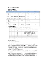
5.1 Display Indication 

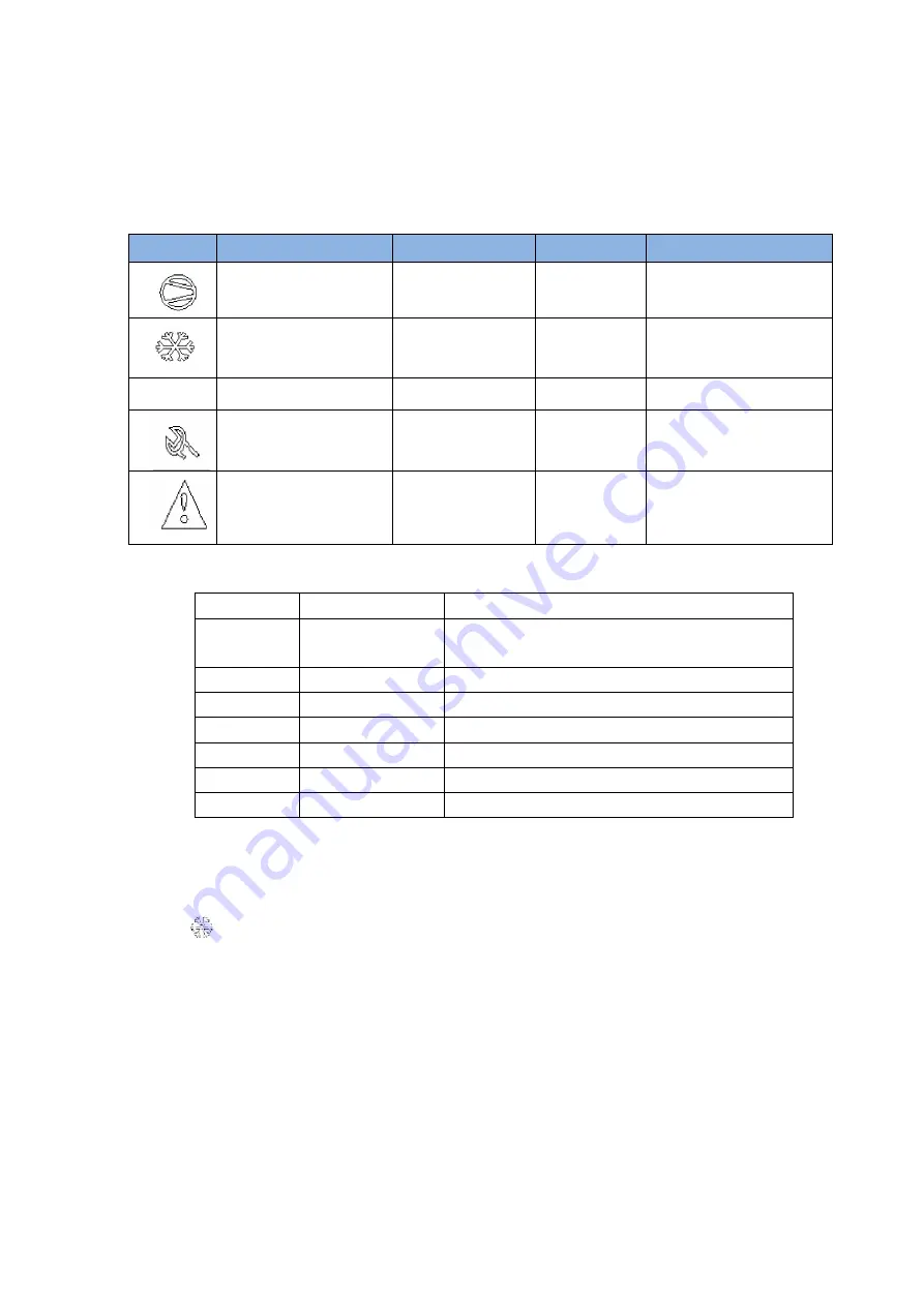
Display Sign Description 

Icon 

Function 

On 

Off 

Blinking 


Load   

On 

Off 

Being delay load output 


Cooling TEMP. Setting 

In the setting state 

---- 

---- 

HACCP 

Heating TEMP. Setting 

In the setting state 

---- 

---- 


Repairing 

Faulty 

No fault 

---- 


Warning 

Warning 

No warning 

---- 

Panel Digit Indication 

Four red digits display the measured temperature and warning code.       

No. 

Display Code 

Warning Information 

E01 

Room temperature sensor fault 

( short circuit or open circuit ) 

Hi 

Temperature exceeds the MAX value 

Lo 

Temperature exceeds the MIN value 

EE 

Data access error 

Err 

Password error 

iA 

External warning 

UnL 

Restore the default password ”1111” 


6.2 Keypad Operation 

  6.2.1 Set coo/heat temperature 

  Keeping 

S

  pressed for 3 seconds to


enter temperature setting mode. The indicator 

              or 

HACCP

is on, and the digital shows the set temperature. Press key 

  or 

  to change the set temperature ( Keeping 

  or 

  pressed, it will be adjusted 

quickly.). Press 

S

, the set temperature will be saved and leave the setting mode. Or do not 

press any key for 30 seconds; the device will leave the set mode without saving the set data.   


6.2.2 Set system parameters 


Enter Into System Parameter Setting Mode 

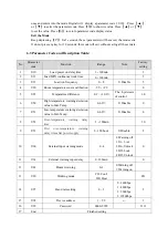
Use  the password to enter into the parameter setting  mode, the factory  password is “1111”. 

Keep 

P

  pressed for 3 seconds to enter the mode. The digital displays 

---0

, then press   

  to the digit of the password, press 

  to the value of the digit, press 

S

  to 

confirm. If the password is wrong, it will shows 

Err

, and returns to the measuring 

temperature states after the buzzer beeping 3 times. If the password is right, the buzzer beeps 

Summary of Contents for ZL-660A-R

Page 1: ...Buzzer alarm output Max high temperature or min low temperature exceed warning Sensor failure warning External warning input Dry contact alarm output RS 485 3 Size Specification 1 Front panel dimension 78 34 5mm 2 Drilling template 71 29mm 3 Whole machines dimension 78 34 5 71mm 4 Length of sensor s 3m including the sensor probe 4 Technical Specification Temperature Sensor NTC Setting Range 40 120...

Page 2: ...at temperature Keeping S pressed for 3 seconds to enter temperature setting mode The indicator or HACCP is on and the digital shows the set temperature Press key or to change the set temperature Keeping or pressed it will be adjusted quickly Press S the set temperature will be saved and leave the setting mode Or do not press any key for 30 seconds the device will leave the set mode without saving ...

Page 3: ...le 5 4 U20 Room temperature sensor calibration 9 9 9 9 0 5 U22 Temperature difference 0 1 10 0 The hysteresis of control 1 0 6 U50 High temperature warning deviation value to Max Temp 0 60 0 Disable 0 7 U51 Low temperature warning deviation value to Min Temp 0 60 0 Disable 0 8 U52 Over temperature warning delay time 1 180min 30 9 U53 First over temperature warning delay time after power supply 0 1...

Page 4: ...ture Sensor Fails When the room temperature sensor fails the system will automatically run into the protected running mode In this mode the compressor will run and stop with the period of 30 minutes Compressor works for U12 3 minutes stops for 30 U12 3 minutes For example Set U12 is 3 when the temperature sensor fails compressor runs for 9 minutes and then stops 21 minutes move in circles If U12 0...

Page 5: ... and Password Keep P and keys pressed for 5 seconds the device displays UnL press twice buzzer sounds system auto restores the default parameters and password 1111 8 Controller Installation 8 1 Warning Avoid installing the device in the following environment Relative humidity is greater than 90 or possibly dewing Strong vibration Possibility be dropped or within fog Exposed to eroding and pollutin...

Page 6: ...power devices Avoid direct contact with the internal electronic components After finish and check the electrical wiring layout before connect them to the device please follow this instruction Pay attention the electrical wiring diagram below wrong connection possibly damages the device and the system and may be dangerous to the user All security and protecting device for the equipments are necessa...

Page 7: ......

Reviews: