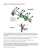
Adjusting the Orifices Plate Gap Setting (Split Head Design)
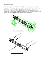
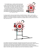
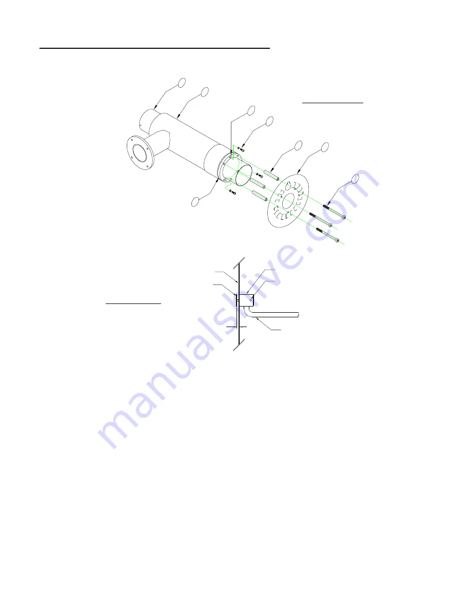
Figure 3: Gas Manifold
1
2
4
5
6
7
8
3
1. Primary Air Tube
2. Gas Manifold
4. 3 ea. Jam Screw / Washer
3. 3 ea. Gap Adjusting Screw
8. Adjustible Orifice Plate
7. 3 ea. Diffuser Fastening Screw
6. Diffuser Plate
5. 3 ea. Diffuser Spacer
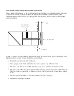
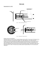
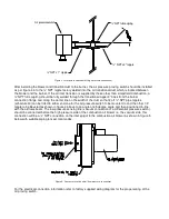
Figure 4: Pilot Injector
Diffuser Face
1/ 8" (3mm)
Pilot Injector Disc
Pilot Injector Body
Set Screw
Pilot Gas Supply Line
To alter the orifice plate gap setting, the gas manifold (item 2) must first be removed from the burner. To do
this, follow the procedure outlined on the previous page. Once the gas manifold has been removed, the
diffuser (item 6) must be removed. Once removed, the service person has access to the adjustable orifice
plate (item 8).
Step 1: If the burner is equipped with a proven gas pilot (Lc21-310), the pilot injector disc must be removed.
Loosen set screw to allow for removal of the pilot injector disc assembly (figure 4).
Step 2: Remove 3 ea. Diffuser fastening screws (item 7) and diffuser stand off pillars (item5).
Step 3: Loosen 3 ea. Jam screw/washer (item 4) on the orifice plate.
Step 4: To DECREASE the gap setting, rotate the gap adjusting screw (item 3) clockwise as illustrated in
Figure 5 on the next page. To INCREASE the gap, rotate counter-clockwise. Using a measuring scale or gap
gauge, adjust all three screws so that the gap setting is equally maintained around the circumference of the
assembly. The orifice plate is free to slide along the primary air tube (item 1).
(Instructions continue on next page.)
Summary of Contents for LC Series
Page 3: ...Section 1 Legal statements and Disclaimers Burner assembly area ...
Page 7: ...Section 2 Burner Technical Data Gas flame firing at 12 300 000 btu hr ...
Page 9: ...Section 3 Component Information General assembled burner ...
Page 11: ...Section 4 Gas Manifold assembly Split gas head assembly ...
Page 16: ...Section 5 Oil Gun assembly Oil nozzle and lance assembly ...
Page 19: ...Section 6 Electrode settings Pilot injector and ignition setup ...
Page 22: ...Section 7 Burner Installation Limpsfield LC9 dual fuel burners on Hurst boilers ...
Page 24: ...Sample Typical fire tube installation ...
Page 25: ...Typical water tube installation ...
Page 29: ...Section 8 Typical Gas control Train 2 gas control train assembled ...
Page 32: ...Section 9 Typical Oil Train Assembled oil pump with filter ...
Page 36: ...Section 10 General start up procedure ...
Page 43: ...Section 11 Service Recommendations ...
Page 47: ...Section 12 General Burner Servicing Procedure ...
Page 52: ...Section 13 Fault Finding ...


