9. If the burner fails to start during the normal start up procedure do not repeatedly recycle the burner
until the failure to start has been identified and rectified, this is to ensure that any unburned fuel is not
deposited into the boiler combustion chamber.
10. The Limpsfield burner cycle/sequence will be controlled by the Autoflame Micro Modulation flame
safeguard. The specific instructions for the operation of this flame safeguard are supplied to the
trained technician during Autoflame training and can also be supplied from Limpsfield Engineering on
request.
11. The correct combustion test equipment such as combustion gas analyzer, manometers, electrical
testers etc. should be used to ensure the burner package is set up for reliable operation whilst
maximizing end user safety.
12. Any combustion adjustments made to either the fuel or air controls to achieve the required input must
be made using a calibrated combustion analyzer, a visual check to ensure that the flame is stable
must also be made.
13. On completion of the start up/commission of the burner package, the Limpsfield Commissioning
Report (found at the rear of the O & M manual in section 17) should be filled in completely, copy’s
should be sent to the end user, held by the commissioning technician and sent to Limpsfield
Engineering.
General Information
The burner air damper and combined oil/gas valves are operated by individual servo motors, these servo
motors can be accurately set to any position between 0 and 90 angular degrees. The commissioning
process is fully described in the Autoflame Technical Manual section 2. The air damper and fuel valves can
be programmed for a minimum of 5 positions or up to a maximum of 17 positions. Each position should be
set
up to provide clean and efficient combustion from low to high fire. The air damper and fuel valves are driven
to the correct position(s) to provide good combustion and electronically entered and locked into the
Autoflame Micro Modulation Flame safeguard in order that when operating and modulating under normal
conditions the same safe and efficient combustion is met at all times.
The servo motors controlling the air and fuel (Gas or Oil) should be set to achieve a smooth and reliable light
off every time, once this is achieved the burner flame will modulate to meet the boiler load demand based on
the settings programmed and entered by the trained commissioning engineer into the Autoflame Micro
Modulation and flame safeguard. The high fire position is also locked into the electronic memory of the
Autoflame Micro Modulation flame safeguard therefore ensuring that the high input position cannot be
increased by the operator.
The gas is introduced via a dual gas shut off valve assembly and gas pressure regulator; this controls the
on/off control of the gas as well as ensuring that the gas is supplied at a constant pressure to the burner.
The gas volume is controlled using a butterfly gas metering valve and servo motor assembly.
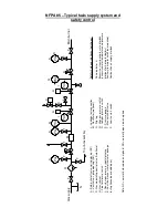
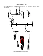
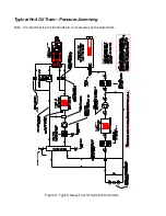
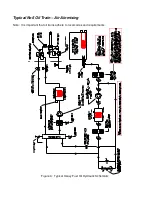
The oil is introduced via a dual oil shut off valve assembly and an oil pump complete with oil pressure
regulator; this controls the on/off control of the oil as well as ensuring that the oil is supplied at a constant
pressure to the burner. The oil volume is controlled using a V slot oil spillback valve and servo motor
assembly. The V slot oil valve is situated in the return oil line from the nozzle, this controls the amount of oil
spilling back to the oil pump or oil supply. The spillback pressure controls the amount of oil being passed
through the oil nozzle therefore controlling the firing rate.
Note: In the case of dual fuel burners; the oil and gas valve metering devices are direct coupled and
controlled by one servo motor for the fuel control and one for the air damper control. When the burner is gas
firing the oil V slot valve will also open/close as they are direct coupled but the main oil shut off valves remain
closed therefore no oil is allowed to flow to the nozzle. When the burner is oil firing the gas butterfly valve
will also open / close as they are direct coupled but the main gas shut off valves remain closed therefore no
gas is allowed to flow to the gas head.
Summary of Contents for LC Series
Page 3: ...Section 1 Legal statements and Disclaimers Burner assembly area ...
Page 7: ...Section 2 Burner Technical Data Gas flame firing at 12 300 000 btu hr ...
Page 9: ...Section 3 Component Information General assembled burner ...
Page 11: ...Section 4 Gas Manifold assembly Split gas head assembly ...
Page 16: ...Section 5 Oil Gun assembly Oil nozzle and lance assembly ...
Page 19: ...Section 6 Electrode settings Pilot injector and ignition setup ...
Page 22: ...Section 7 Burner Installation Limpsfield LC9 dual fuel burners on Hurst boilers ...
Page 24: ...Sample Typical fire tube installation ...
Page 25: ...Typical water tube installation ...
Page 29: ...Section 8 Typical Gas control Train 2 gas control train assembled ...
Page 32: ...Section 9 Typical Oil Train Assembled oil pump with filter ...
Page 36: ...Section 10 General start up procedure ...
Page 43: ...Section 11 Service Recommendations ...
Page 47: ...Section 12 General Burner Servicing Procedure ...
Page 52: ...Section 13 Fault Finding ...

