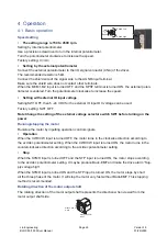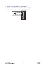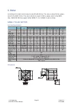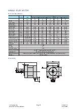
BLDC50/100
User Manual
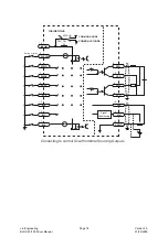
SPST(Speed-set)
OFF Internal speed setting
ON External analog signal setting
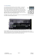
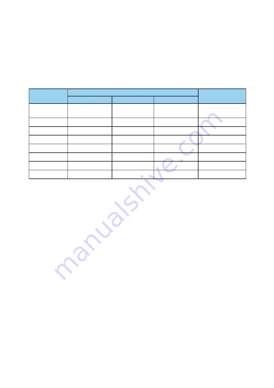
Multi-speed operation (M0,M1,M2)
8 kinds of speed is available with M0, M1, M2 input. (Speed control mode and position control
mode share the same function)
Default
operating data
Operating speed selection
Speed setting
method
M0
M1
M2
0rpm
OFF
OFF
OFF
Internal speed
setting
500rpm
ON
OFF
OFF
Digital setting
1000rpm
OFF
ON
OFF
Digital setting
2000rpm
ON
ON
OFF
Digital setting
3000rpm
OFF
OFF
ON
Digital setting
3500rpm
ON
OFF
ON
Digital setting
4000rpm
OFF
ON
ON
Digital setting
4500rpm
ON
ON
ON
Digital setting
STOP
When STOP is on, the motor stops in the mode set by STMD.
Output Signal Description
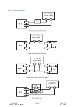
FAULT
FAULT output an error signal when the drive is over-heat, over-current, over-voltage, under-volt-
age or internal voltage bad. The output voltage of error signal can be defined by SCL command
AO.
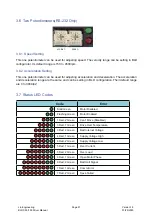
SPEED OUT
The motor output shaft output
6*(pole pairs) per revolution(default). And the pulse number can be set through the software.
MOVE
This signal is output during motor rotation.
VA
Speed reached command. If the difference between the actual motor speed and the input speed
reaches specified range, the drive will output this signal. The difference range can be defined in
0~+/-400rpm (the default range is +/-200rpm).
FAULT2
In order to avoid overload, the drvie can set the overload level, and use it as overload alarm sig-
nal. With this signal, user can distinguish the real cause of fault or warning.
Lin Engineering
BLDC 50/100 Driver Manual
Page 13
Version 1.0
01/29/2020


