BLDC50/100
User Manual
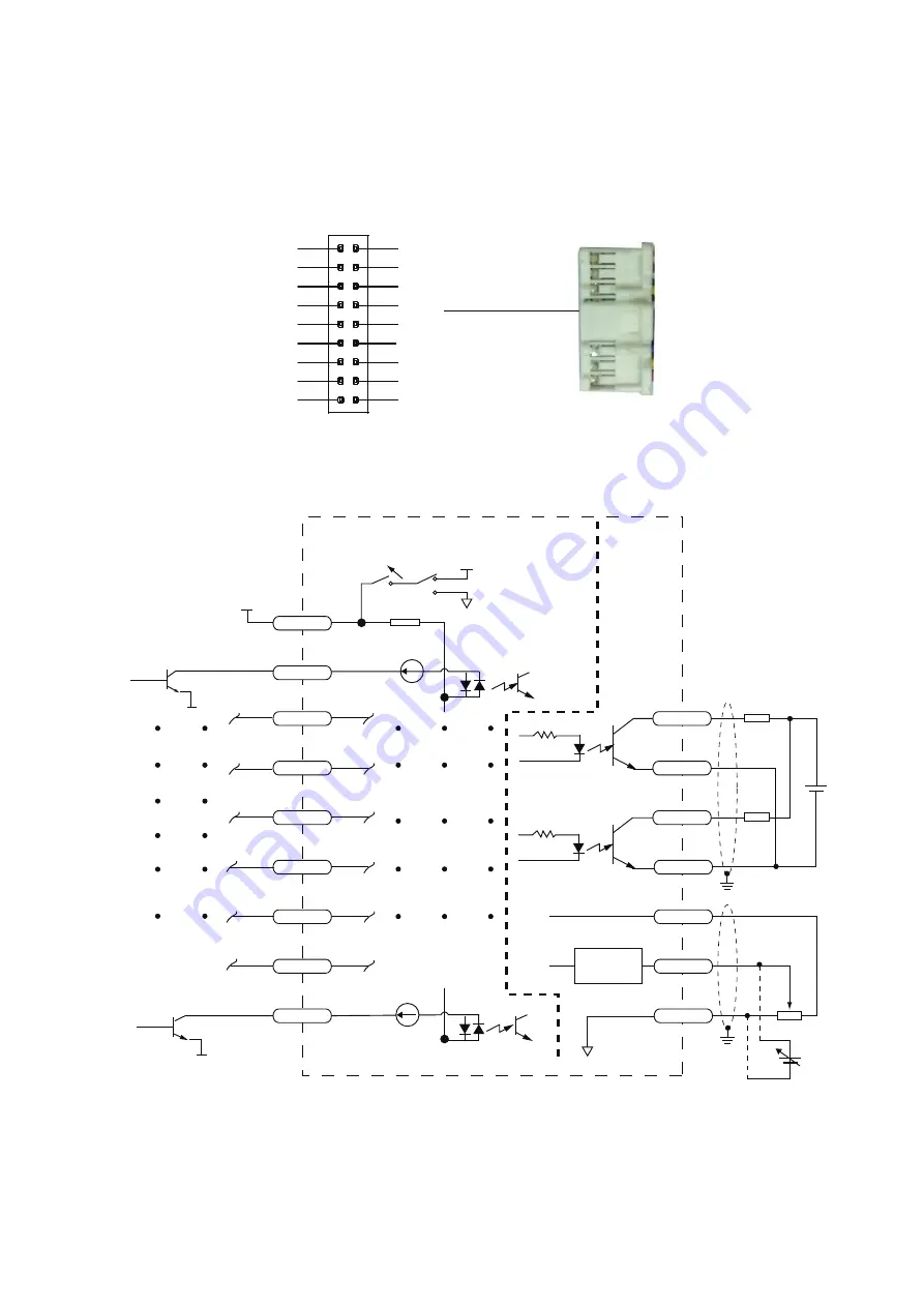
3.5 Connecting the Inputs and Outputs(CN4)
The connector is an 18-Pin board-to wire connector with secure locking device and designed to
2.0 mm pitch, crimping style and double-row. The pin-out is as follows:
3.5.1 Input Connection
M2
M1
M0
STP
SPST
EN/RE
STMD
CW/CCW
5V
17
15
13
11
9
7
5
3
1
18
16
14
12
10
8
6
4
2
INCOM
AGND
AIN
5V
SPO-
SPO+
FLT-
FLT+
GND
CN4
CONTACTS: JST SPUD-001T-P0.5
HOUSING : JST PUDP-18V-S
Connect to CN4
INCOM
COMMON CATHODE
COMMON ANODE
CW/CCW
STMD
EN/RE
SPST
STP
M0
M1
M2
AGND
AIN
+5V
FLT-
FLT+
SP0-
SP0+
18
0 V
0 V
8
SW1 OFF 5V
10
4
6
12
14
16
3
5
7
9
11
13
15
17
Signal
Conditioning
3K
inside drive
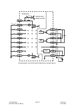
Connecting to control IO with external Sinking Outputs
5-24V
Lin Engineering
BLDC 50/100 Driver Manual
Page 15
Version 1.0
01/29/2020


