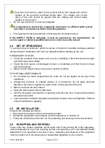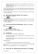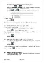
background image

IS792  ECN 4879 

Page 15 of 37 


•"stand-by"  (the  device  is  switched  on  and  no  operating  cycle  is  running,  but  it  is 
possible to select one) 
•"off"  (the  device  is  switched  off  and  no  operating  cycle  is  running,  and  it  is  not 
possible to select any).  

If power is interrupted while in the "on" mode, when power is restored the device will be in 
the same state and the operational cycle will be restarted from the point reached when the 
power interruption occurred. 

If power is interrupted while in "stand-by" or "off" mode, when power is restored the device 
will be in the same state. 


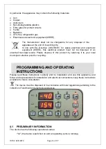
4.2  SWITCHING THE DEVICE ON/OFF ("off"/"stand-by") 

Ensure no procedures are running 

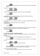
•press 

B1

 for 5 s 

The  displays  will  blink  for  few  seconds  than  the  upper  display  will  show  the  actual  air 
temperature inside the cavity. 
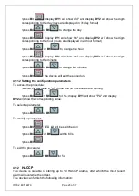
In order to switch off the controller, press and hold the 

B1

key for 5 secs, the upper display 

will show the 

OFF

label. 


4.3  STARTING/STOPPING AN OPERATIONAL CYCLE ("on"/ "stand-
by") 

In order to stop an ongoing cycle 

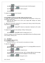
•press 

B1

 and release 

the controller will switch into the stand-by mode. 
The regulators are switched off while in "stand-by" mode. 


4.4  THE DISPLAY  

In the "on" state, during normal operation, display 

DY1

 shows: 

•the  temperature  measured  by  the  needle  probe  if  a  set-temperature  chilling  or 
freezing cycle is ongoing 

•the temperature of the cabinet if a set-temperature chilling, or timed freezing or a 
storage cycle is ongoing. 

Display 

DY2

 shows: 

•the elapsed time for a blast chill or freezing cycle, if these are ongoing 

While  in  "stand-by"  mode,  display 

DY1

  shows  the  cabinet  temperature  and  display 

DY2


shows "- - -". 
While in "off" mode, display 

DY1

 shows "OFF" and display 

DY2

 is off. 


4.5  DISPLAYING THE TEMPERATURES DETECTED BY THE PROBES 

Summary of Contents for BGBF-10

Page 1: ...LER FREEZER BGBF 5P BGBF 10 Please make a note of your product details for future use Date Purchased _________________________ Model Number __________________________ Serial Number ___________________...

Page 2: ...INSTRUCTIONS 14 4 1 PRELIMINARY INFORMATION 14 4 2 SWITCHING THE DEVICE ON OFF off stand by 15 4 3 STARTING STOPPING AN OPERATIONAL CYCLE on stand by 15 4 4 THE DISPLAY 15 4 5 DISPLAYING THE TEMPERAT...

Page 3: ...tion parameters 23 4 13 VIEWING HACCP ALARM INFORMATION 24 MAINTENANCE AND CLEANING 25 5 1 ROUTINE MAINTENANCE 25 Cleaning the interior and exterior of the appliance 26 Condenser cleaning 26 ALARMS AN...

Page 4: ...rry warning symbols caution symbols and notices Ensure that these are understood at all times WARNING This symbol is used whenever there is a risk of personal injury CAUTION This symbol isused wheneve...

Page 5: ...on at all times Particular attention must be paid to safety warnings refer to Section 1 5 Routine maintenance technician qualified operator able to perform routine maintenance of theequipment by follo...

Page 6: ...brushes abrasive cleaners or strong alkaline solution on any surface The relocation of the unit must be performed by qualified personnel Do not shift the refrigerator from side to side as this may cr...

Page 7: ...E SHELF PERIMETER 1 9 RULES OF USAGE Do not stack foods that need to be blast chilled and or frozen Do not exceed the declared number of kilograms and distribute the product evenly in the trays Blast...

Page 8: ...ge to low voltage power Do not modify or use power supplies other than OEM equipment Connection of the power supply may require a properly grounded receptacle Potential for electrical shock or equipme...

Page 9: ...Flammable refrigerant used Follow handling instruction carefully To be repaired only by trained service Personnel Do not puncture Refrigerant Tubing Refrigerating Equipment intended for laboratory use...

Page 10: ...IS792 ECN 4879 Page 10 of 37 Service markings Label located near the cooling unit compartment Disposal Marking attached upon the exterior of the cabinet Max high load...

Page 11: ...C Hard blast chilling cycle o First step air set at 0 C o Second step air set at 20 C Shock freezing cycle Manual with Air set at 40 C Model Blast chilling power consumption kW Shock freezing power co...

Page 12: ...from the sides where the air inlets and outlets are located The room must be well ventilated Keep well away from sources of heat Avoid direct sunlight Remove packing material Remove accessories from i...

Page 13: ...properly Make sure all copper tubing unions are in perfect condition FOR OPTIMAL PERFORMANCE Do not block the motor compartment air vents Do not lay objects on the top of the equipment Arrange the pro...

Page 14: ...not be disposed of as unsorted municipal waste Please dispose of this product by returning it to your local municipal collection point for recycling PROGRAMMING AND OPERATING INSTRUCTIONS Please read...

Page 15: ...mperature inside the cavity In order to switch off the controller press and hold the B1key for 5 secs the upper display will show the OFFlabel 4 3 STARTING STOPPING AN OPERATIONAL CYCLE on stand by In...

Page 16: ...nd no procedures are running press B11 the display DY1 will show dEF If the evaporator temperature is above the value set by parameter P23 8 mins from factory defrosting will not be activated To stop...

Page 17: ...the following operational cycles hard set temperature chilling and storage normal set temperature chilling and storage set temperature freezing and storage hard timed chilling and storage timed normal...

Page 18: ...de To interrupt the cycle press B1 4 10 2 Normal set temperature chilling and storage cycle To select the cycle ensure the device is in off mode and no procedures are running press B8 display DY1 will...

Page 19: ...storage cycle To select the cycle ensure the device is in off mode and no procedures are running press B7 display DY1 will show the operational set point and LED L7 will switch on To adjust the first...

Page 20: ...l show the operational setpoint and LED L8 will switch on To adjust the operational setpoint press B4 or B6 It is also possible to set the operational setpoint by means of parameter P4 press B3 displa...

Page 21: ...When the freezing step duration time has elapsed the buzzer is activated for the length of time set by parameter P55 and the device switches to storage mode To interrupt the cycle press B1 4 10 7 Sto...

Page 22: ...play DY1 shows the temperature measured by the needle probe for 5s To display the time elapsed since starting a chilling or freezing step press B4 display DY2 shows the elapsed time for 5 s If the key...

Page 23: ...utes press B4 or B6 to change the minutes press B3 the device will exit the procedure 4 11 2 Setting the configuration parameters To access the procedure ensure the device is in off mode and no proced...

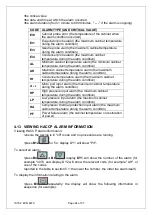
Page 24: ...ition d r Micro port input alarm the maximum cabinet temperature during the alarm condition HP High pressure input alarm the maximum cabinet temperature during the alarm condition LP Low pressure inpu...

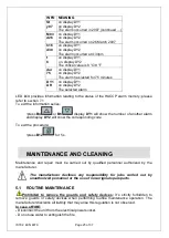
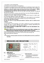
Page 25: ...s press B4 or B6 display DY1 will show the number of another alarm and display DY2 will show the corresponding code To exit the procedure press B12 for 5 s MAINTENANCE AND CLEANING Maintenance and rep...

Page 26: ...clean with steel wool pads Do not use cleaners not specifically intended for stainless steel on stainless steel surfaces Condenser cleaning The condenser is a heat exchanger If it is dirty or clogged...

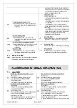
Page 27: ...ongoing L12 Program LED if permanently on program storing selection or execution is ongoing L13 HACCP LED if permanently on program storing selection or execution is ongoing 6 2 INDICATIONS dEF if per...

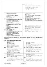
Page 28: ...the input activation Consequences the operational cycle will be restored from the point where the power failure occurred When the cause that triggered the alarm has been resolved the device restores...

Page 29: ...ational setpoint during freezing cycle with reference to the cabinet probe 40 P6 Operational setpoint during Hard chill cycle first step with reference to the cabinet probe 20 P7 Operational setpoint...

Page 30: ...P29 Resetting of compressor protections at start of defrosting only if P22 1 1 YES 0 P30 Elapsed time between the defrost request and switching on the compressor only if P22 1 and providing that the...

Page 31: ...vity in the absence of the condenser probe P61 0 0 in parallel with compressor 1 on 1 P52 The temperature below which the condenser fan is switched off in the presence of the condenser probe P61 1 and...

Page 32: ...t of measurement is degrees Celsius or degrees Fahrenheit 2 The unit of measurement depends on parameter P0 3 The test result is positive if the difference between the temperature measured by the need...

Page 33: ...s no effect during UV light switch on cabinet sterilisation 10 Altering parameter P73 is effective on exiting the configuration parameter setting procedure as soon as you will quit the configuration p...

Page 34: ...E SWITCH 22 FUSE 500V 10 3x38 16A 23 FUSE HOLDER 10 3x38 UL 24 MAGNETIC DOOR SWITCH 25 DISPLAY KEYBOARD MOD 2D 26 CONTROLLER POWER BOARD 27 NET FILTER 28 COMPRESSOR POWER RELAY 29 DISPLAY STICKER DESM...

Page 35: ...300mm 7 CASTOR W OUT BRAKE 8 SWIVEL CASTOR W BRAKE 9 NOT USED 10 CONDENSATE TRAY 11 CONTACTOR 12 FUSE 10 3x38 500Vac 20A 13 FUSE HOLDER 10 3x38 UL 14 MAGNETIC DOOR SWITCH 15 BLAST CHILLER KEYPAD STIC...

Page 36: ...ontact our service department UK 01522 875520 For non UK customers please contact your local Lincat dealer All service work other than routine cleaning should be carried out by one of our authorised s...

Page 37: ...age due to incorrect installation modification unauthorised service work or damage due to scale food debris build up etc The manufacturer disclaims any liability for incidental or consequential damage...

Reviews: