background image

IS 592   ECN 3855 

Page 12 of 13 


Burner will not light 


Part Number 

Description 

Used on 

BU75 

Burner 

ALL 

CO113 

Copper washer 

IG06 

Igniter lead 

IG14 

Igniter electrode 

IG35 

Igniter piezo 

IG37 

Ignition earth lead 

KN510 

Control knob 

FE40 

Adjustable leg 

PI25 

Pilot assembly 

SC01 

Scraper 

TC03 

Thermocouple 

TC05 

Thermocouple lock nut 

TC06 

Thermocouple sleeve 

TC24 

Thermocouple capillary 
lock nut 

TH202 

Thermostat 

WA08 

Fibre washer 


SPARE PARTS LIST


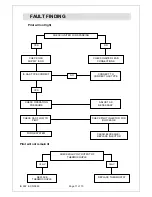
CHECK SUPPLY PRESSURE IS CORRECT 

CHECK GAS FLOW TO 

BURNER 

YES 

NO 

ADJUST AS NECESSARY 

CHECK BURNER INJECTOR 

FOR BLOCKAGE 

REPLACE 

THERMOSTAT 

CLEAR BLOCKAGE / 

REPLACE INJECTOR 

Summary of Contents for Opus 800 OG8201

Page 1: ...1 OG8201 R OG8201 C OG8202 OG8202 R OG8202 C Please make a note of your product details for future use Date Purchased _________________________ Model Number __________________________ Serial Number __...

Page 2: ...rvice Information and Guarantee 14 IMPORTANT INFORMATION Read these instructions carefully before using this product paying particular attention to all sections that carry warning symbols caution symb...

Page 3: ...services before cleaning or servicing maintenance TECHNICAL DATA OG8201 OG8202 Dimensions Height mm 530 Width mm 600 900 900 900 Depth mm 800 Weight Kg 82 5 98 0 105 98 0 Plate weight Kg 45 53 0 60 5...

Page 4: ...bstances harmful to health in the room of installation There must be a minimum free area of 4 5cm2 per kW of total heat input Allow for a sufficient flow of fresh air for complete gas combustion Do no...

Page 5: ...per hour per kW of installed capacity If the appliance must be fitted near walls partitions kitchen furniture etc we recommend they are made from non inflammable material otherwise they should be cove...

Page 6: ...to the gas supply check for soundness and then purge the appliance by rotating all control knobs to the ignition position and depressing them Hold the knobs depressed to purge the supply pipe and inte...

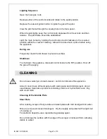
Page 7: ...check the fat drawer to prevent overflow Shutdown To shut down the appliance rotate all control knobs to the Off position Shut off the gas at the supply CLEANING Do not use a water jet or steam cleane...

Page 8: ...be carried out by one of our recommended service engineers The griddle plate is very heavy and assistance will be required to raise and remove the plate from the appliance Care must be taken to avoid...

Page 9: ...the thermostat Remove the clamp from the manifold to free the thermostat Feed the capillary and bulb from the thermostat through the bulkhead Fit the new thermostat and make good all connections Perf...

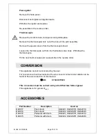
Page 10: ...raw the thermocouple Fit the new thermocouple and re assemble in the reverse order This appliance cannot be converted by the user For conversion kit and instructions of how to convert contact Lincat d...

Page 11: ...IS ON CONNECT TO CORRECT GAS TYPE YES YES NO CHECK IGNITER LEAD CONNECTIONS IS GAS TYPE CORRECT ADJUST AS NECESSARY CHECK PILOT INJECTOR FOR BLOCKAGE CLEAR BLOCKAGE REPLACE INJECTOR NO CHECK OPERATIN...

Page 12: ...d KN510 Control knob FE40 Adjustable leg PI25 Pilot assembly SC01 Scraper TC03 Thermocouple TC05 Thermocouple lock nut TC06 Thermocouple sleeve TC24 Thermocouple capillary lock nut TH202 Thermostat WA...

Page 13: ...ot diminish your statutory or legal rights The guarantee does not cover Accidental damage misuse or use not in accordance with the manufacturer s instructions Consumable items such as filters glass bu...

Reviews: