IS355 ECN3592
6
A
B
F
C
D
E
GAS SUPPLY AND CONNECTION
Check that the gas supply corresponds to that specified on the data plate.
Connection is at the rear of the unit via a 1/2" G male thread. If connection to the supply
pipe is via a flexible hose, ensure that the hose used is suitable for commercial catering
appliances. The hose shall be periodically examined and replaced as necessary.
WARNING: Black domestic hoses are not suitable for this appliance
Connection shall comply with local regulations.
When making the connection to the appliance, secure the hexagon on the fitting to prevent
rotation of the internal pipe work. An isolating cock should be fitted into the supply line
close to the unit, for emergency shutdown or servicing purposes.
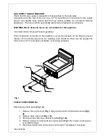
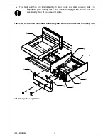
Fig 1
FASCIA PANEL REMOVAL
Removing the facia panel
(Fig 1, A)
1. Remove the control knob
(Fig 1, C)
and undo control thermostat screws
(Fig1,
E)
.
2. Remove drain valve nut
(Fig 1, D)
.
3. Point the drain valve lever directly forward
(Fig 1, B)
.
4. Remove screws from beneath the control panel
(Fig 1, F)
to allow control panel
to be lifted forward
5. Disconnect igniter lead and remove control panel completely if necessary
Summary of Contents for Silverlink 600 DC04
Page 20: ...IS355 ECN3592 Notes...

