IS355 ECN3592
7
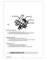
A
B
C
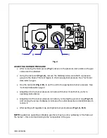
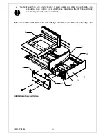
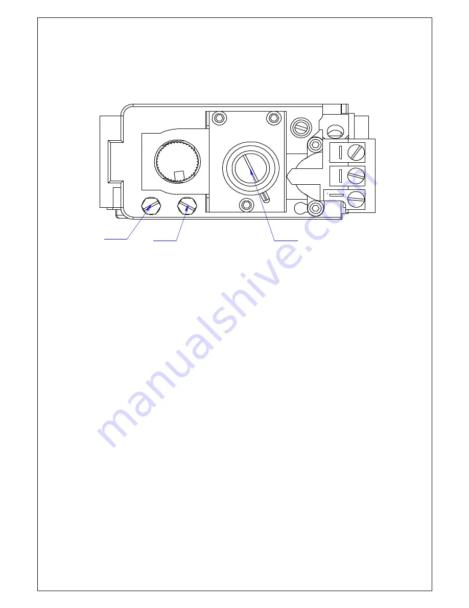
Fig 2.
ADJUSTING BURNER PRESSURE
After removing the facia panel,
(Fig 1)
access to the pressure test points on the gas
valves can be obtained.
Using the test point
(Fig 2, A),
remove the blanking screw and attach a pressure
gauge to the boss of the test nipple, to check supply inlet pressure. See
“technical
data table
” page 4.
Use the test point
(Fig 2, B),
to set the unit to the appropriate burner pressure. See
“technical data table” page 4.
Adjustment to the burner pressure is made with burner lit and full on, (refer to
operating instructions)
Adjustment of the burner pressure is made by removing the governor cap
(Fig 2, C)
and turning the screw clockwise to increase the outlet pressure and anticlockwise to
reduce it.
After setting refit regulator cap and tighten test point screws
(Fig 2, A, B, C)
NOTE:
appliances operating on Butane gas there may be some „yellowing‟ of the flame at
the burner
– this is normal owning to the composition of the gas.
Summary of Contents for Silverlink 600 DC04
Page 20: ...IS355 ECN3592 Notes...

