IS 358 ECN 3592
6
INSTALLATION INSTRUCTIONS (Continued).
PRESSURE SETTING
Note: For model J10, set the pressure for each side independently.
1.
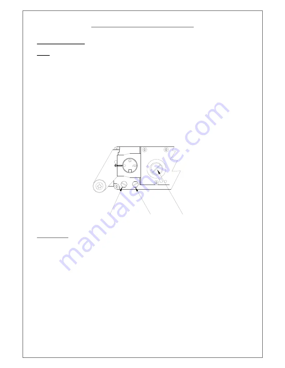
Use the test point provided on the gas control valve marked “IN”
(Fig 1, A)
,
to check the supply
inlet pressure. (Refer to technical data table on page 16).
Note : An external regulator should be
fitted to the fryer if the inlet pressure exceeds 50mbar
2.
Use the test point marked “OUT”
(Fig 1, B)
, to set the unit to the appropriate burner pressure.
3.
Adjustment is made via the valve‟s onboard governor, which is situated centrally on the valve.
(Fig 1, C).
4.
Remove the governor cap and turn the screw clockwise to increase the outlet pressure and
anticlockwise to reduce it.
5.
With main burner lit, (refer to operating instructions, page 9), adjust the burner pressure by the
method described above
to the value shown on the technical data table, page 16.
6.
After setting, ensure the governor cap is properly secured and the blanking screws replaced in
the test points.
Fig 1.
HEAT INPUT.
The total nominal gross heat input for the appliances are as follows:-
Models J5 and J10
Propane gas............. 11. / 22.04 kWh
Natural gas.............. 11.5 / 22.79 kWh
A
B
C


