background image

OPERATION

APEX

®

 3 SERIES MIG PENDANT MANUAL

B-2

Pendant Operation

The APEX 3 Series Pendant is designed around full 
functionality and easy operator experience. The pen-
dant’s buttons serve multiple purposes, depending on 
the screen display. See 

FIGURE 4 - Pendant Items on 

page B-3 


to review each button, knob and switch on 

the pendant. 

Button Actions

Each of the buttons and toggles may perform 
differently depending on how the buttons are pressed. 
Listed below are the four types of button presses.

1. SHORT PRESS


     A short press is a standard press that engages the 

button and is not held in place. Most operations are 
performed as a short press. 

Example: Quickly pressing down button 7 will center the 
oscillator.

2. LONG PRESS 

     For some screens, holding a button down for a 

length of time exceeding two seconds signals the 
system to perform an alternate function.

Example: A long press of more than two seconds on but-
ton 7 will start the oscillation test mode on some screens.

3. HOLD 

     By pressing and holding down a button or toggle,  

the effects exhibited will continue or speed up.

Example: When pressing button 1 in the jog screen,  
gas will purge for three seconds. Holding down button 1  
will cause the gas to continuously purge.

4. HOLD AND ROTATE

     The steering knob also acts as a button. It can be 

pressed or rotated for different actions for some 
screens. It can also be held down and rotated  
for faster navigation. 

Selection Buttons

Buttons 1 through 5 are selection buttons. Their 
functions change depending on the screen. In each 
screen there will be an icon just above the button to 
indicate its function. A short press enables, disables or 
selects the shown variable.

Navigation Controls

Items 6 through 8 control navigation. They function 
primarily for navigating through the menus and 
changing values while setting up the system. 

Note:  

When welding, steering knob 7 functions  
only for steering or oscillation steering 
if oscillation is enabled. 

6. LEFT TOGGLE (WHITE BORDER) 

• 

Short Press – 

Navigates or changes the selected 

value (in this example, it will change the value in 

the left dwell box) 

• 

Hold – 

Increases or decreases value / change 

speed on some screens

7. STEERING KNOB 

• 

Rotate – 

Steers oscillation in and out or changes 

the selected variable

• 

Short Press – 

Centers the oscillation or moves to 

the next variable

• 

Long Press – 

Starts / Stops oscillation test  

(in idle mode only)

• 

Hold & Rotate – 

Fast navigation between  

selected variables

8. RIGHT TOGGLE (GRAY BORDER) 

• 

Short Press – 

Navigates or changes the selected 

value (in this example, it will change the value in 

the right dwell box)

• 

Hold – 

Increases or decreases value / changes 

speed on some screens

Summary of Contents for 12879

Page 1: ...770 0063 to talk to a Service Representative Hours of Operation 7 00 AM to 5 00 PM PT Mon thru Fri After hours Use Ask the Experts at lincolnelectric com A Lincoln Service Representative will contact you no later than the following business day For Service outside the USA and Canada please call 1 619 628 1022 or e mail us at orbitalsupport lincolnelectric com COVER PAGE FIGURE 8 Save for future re...

Page 2: ...r breathing zone and the general area IN A LARGE ROOM OR OUTDOORS natural ventilation may be adequate if you keep your head out of the fumes See below USE NATURAL DRAFTS or fans to keep the fumes away from your face If you de velop unusual symptoms see your supervisor Perhaps the welding atmosphere and ventilation system should be checked WEAR CORRECT EYE EAR BODY PROTECTION PROTECT your eyes and ...

Page 3: ...eep all equipment safety guards covers and devices in position and in good repair Keep hands hair clothing and tools away from V belts gears fans and all other moving parts when starting operating or repairing equipment 1 e In some cases it may be necessary to remove safety guards to perform required maintenance Remove guards only when necessary and replace them when the maintenance requiring thei...

Page 4: ... lens should conform to ANSI Z87 I standards 4 b Use suitable clothing made from durable flame resistant material to protect your skin and that of your helpers from the arc rays 4 c Protect other nearby personnel with suitable non flammable screening and or warn them not to watch the arc nor expose themselves to the arc rays or to hot spatter or metal FUMES AND GASES CAN BE DANGEROUS 5 a Welding m...

Page 5: ... possibility of the welding current passing through lifting chains crane cables or other alternate circuits This can create fire hazards or overheat lifting chains or cables until they fail 6 h Also see item 1 c 6 I Read and follow NFPA 51B Standard for Fire Prevention During Welding Cutting and Other Hot Work available from NFPA 1 Batterymarch Park PO box 9101 Quincy Ma 022690 9101 6 j Do not use...

Page 6: ...ed in the environment is compatible This may require additional protection measures h the time of day that welding or other activities are to be carried out The size of the surrounding area to be considered will depend on the structure of the building and other activities that are taking place The surrounding area may extend beyond the boundaries of the premises METHODS OF REDUCING EMISSIONS Mains...

Page 7: ...7 SAFETY APEX 3 SERIES MIG PENDANT MANUAL ...

Page 8: ...uttons B 7 Idle Screen Test Weld Modes B 8 Weld Screen B 9 Weld Screen Buttons B 9 Test Screen B 9 Test Screen Buttons B 9 Jog Screen B 10 Jog Buttons B 11 Oscillation Screen B 12 Oscillation Buttons B 13 Setup Menu B 14 Setup Screen Options B 15 Track Setup B 15 Track Type B 15 Track Ring Size B 15 Pipe Size B 15 Heavy Wall Pipes B 15 Positioner Setup B 15 Travel Setup Screen B 16 Travel Pattern ...

Page 9: ...27 Log Out B 27 Operator Log In B 27 Increments Settings B 28 Increment Options B 28 Increment Reference B 29 Programs B 30 Fast Movement B 30 Saving an Independent Pass B 30 Saving a Program Base B 31 Saving a Program Pass B 31 Saving Program Updates B 32 Hide Program Passes B 33 Saving to a USB B 33 Copy to from USB B 33 Deleting a Program B 34 Deleting a Program Base B 34 Loading a Program B 34...

Page 10: ...Save Travel Travel Setup Osc Speed Left Dwell Settings Service Page Swap Shift Case Osc Width Right Dwell Increment Unit Settings Gas Advanced Settings Next Index Travel Direction Positioner ID Track K Kilowatts Wire Feed Travel Direction Wire Wire Feed Speed OD Track Steering Oscillator Wire Retract Travel Direction Previous Index Flat Track Wire Diam eter Pass Travel Direction Add User Direction...

Page 11: ...rdy flat level surface when not in use and be sure to unplug it Keep hands away from weld head wire feeder and other moving parts while in operation Read this entire process and operations manual before using the equipment Only operate the system while on a firm level surface Always verify that the system cart is secured in place before operating the system Keep hands away from weld head wire feed...

Page 12: ...ockwise See FIGURE 1 APEX Pendant Reset Button This reset button can be used to restart the system for troubleshooting purposes and to halt welding and system movement Startup Screen When the system is reset at the Power Wave the screen will display Checking Network Connection Calibrating System FIGURE 2 Startup Screen This is a normal part of the initialization process Note During the start up in...

Page 13: ...usly purge 4 HOLD AND ROTATE The steering knob also acts as a button It can be pressed or rotated for different actions for some screens It can also be held down and rotated for faster navigation Selection Buttons Buttons 1 through 5 are selection buttons Their functions change depending on the screen In each screen there will be an icon just above the button to indicate its function A short press...

Page 14: ... SECTOR Short Press Switches between sectors and changes passes if available on the Increments screen 15 RESET Short Press stops the welding sequence and all motion Twist Release IMPORTANT The reset button is not an emergency stop button Power is still being applied to the system Color Coding The menu buttons and toggles are color coded For example the icons above button 9 are Wire Feed white icon...

Page 15: ...FIGURE 5 Fast Movement Use the steering knob or left and right toggles for naviga tion and selection Use the left toggle or press the steering knob to change from one variable to the next Use the right toggle or turn the steering knob to change the selected variable Press the Enter Selection button when the complete four digit user code has been entered Once a four dig it code is accepted the syst...

Page 16: ...Border Short Press Pressing up or down moves cursor between spaces 7 STEERING KNOB Short Press Moves cursor to the next space Rotation Quickly cycles through available character options Hold Rotate Quickly moves the cursor from one selection to the next 8 RIGHT TOGGLE Gray Border Short Press Pressing up or down changes value of the selection 9 WIRE FEED AMPS No Effect 10 DWELL No Effect 11 OSCILLA...

Page 17: ...s depending on which Menu button has been pressed Pressing the different Menu buttons will change the values shown The different variables shown correspond to the icons on the Menu buttons Similar variables are paired together The variables shown on the screen can be changed using the left and right toggles It is possible to change between these menu options while idle or welding Press the Menu bu...

Page 18: ...g Press Starts stops oscillation test 8 RIGHT TOGGLE Gray Border Changes the value displayed in the top right box in this example it will change the value in the right dwell box 9 WIRE FEED AMPS Short Press Wire Feed Amps options Long Press Navigates to the Jog Screen 10 DWELL Short Press Dwell options Long Press Navigates to the Jog Screen Dwell 11 OSCILLATION Short Press Oscillation options Long...

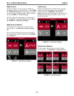
Page 19: ... in Static Screen Items There are many icons common through the Idle Weld and Test screens These items give helpful information to the user throughout the setup and welding process 1 Arc Time Indicates the amount of time spent welding 2 Heat Input Displays the amount of heat input for the current weld in kilojoules in or kilojoules cm 3 Sector Displays the current sector in the weld program if app...

Page 20: ...ns work similar to the Idle screen buttons see Idle Screen section on page B 7 Pressing the Start Stop button during the weld halts the weld and moves into the Jog Menu See FIGURE 16 on page B 11 Test Screen Similar to the Weld Screen the Test Screen will show voltage and amperage feedback but the feedback values will be zero FIGURE 12 Test Screen Options Pressing the menu buttons will move the us...

Page 21: ...screens From the Idle Screen press and hold the Wire Feed Amps or the Travel Voltage menu buttons to enter the Jog Menu The screen above FIGURE 14 Engaging Jog Mode provides for moving the weld head along the track adjusting torch height purging gas and shows the icons for both cold feed forward and cold feed reverse Press the Exit selection button to return Idle screen as shown below FIGURE 14 En...

Page 22: ...Press Travels forward or backward slightly Hold Travels forward or reverse and ramps travel speed 7 STEERING KNOB Rotate Moves the oscillation in and out Short Press Centers the oscillation Long Press Starts stops oscillation test 8 RIGHT TOGGLE Gray Border Short Press Adjusts the torch up and down Hold Adjusts the torch up and down and ramps adjustment speed 9 WIRE FEED AMPS No Effect 10 DWELL Sh...

Page 23: ...well Menu Button will present the user with the option to change the left and right dwells In either screen use a short press to switch between Oscillation and Dwell The items highlighted in red are the variables that can be changed Press the Swap Selection Button to be taken to the Travel Setup Screen Travel Setup is discussed in the Travel Setup Screen section on page B 16 This screen allows the...

Page 24: ...n test 8 RIGHT TOGGLE Gray Border Short Press Increases or decreases Right Dwell time or Oscillation Speed Hold Increases or decreases value continuously 9 WIRE FEED AMPS Short Press Navigates to Jog Menu 10 DWELL Short Press Switches to Dwell option when in Oscillation option otherwise no effect 11 OSCILLATION Short Press Switches to Oscillation option when in Dwell option otherwise no effect 12 ...

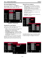
Page 25: ...ack to the Idle screen Setup Screen Options Track Setup employs internal or external track flat track and the size of the pipe where applicable Travel Setup change the steering controls based on where the operator is standing in relation to the track and set up the weave pattern Process Setup sets up the weld process Start Settings adjustment specific to the programs affecting how the system will ...

Page 26: ...se Entering the correct value for track and pipe size ensures accurate travel speed Heavy Wall Pipes Heavy wall pipes may require the user to change the pipe size in later passes Example A 20 inch Schedule 120 pipe has an OD of 20 inches and an ID of 17 inches The pipe diameter for the root pass should be entered as 17 00 inches then increased as the weld progresses outward This will help to maint...

Page 27: ...ions refer to the weld head and are in relation to the user s view facing the weld head 1 Facing Right Traveling Down 2 Facing Left Traveling Down 3 Facing Right Traveling Up 4 Facing Left Traveling Up Travel Pattern The second field the operator can choose is the weave pattern There are three options to choose from No Weave When no weave is selected the oscillator does not move during the welding...

Page 28: ...urned on Travel Speed Sets the electrode travel speed Enabling a sector presents the process variables for that sector With only one sector selected the Idle Weld and Test screens will not show the sector icon Weave Process Options Weave Refer to the Travel Pattern section on page page B 16 for the different weave options Oscillation Width Determines the width of the oscillation weave limited by t...

Page 29: ...prompted to select the wire size type process and then gas type Mode Select guides the user through the settings Selecting a wire diameter moves to wire type See FIGURE 20 Manual Mode Select Selecting wire type leads to a specific process and then to gas selection Each selection filters the list of available weld modes to match your application A cored wire would not allow the user to select an ST...

Page 30: ...le options are based on the selected weld mode See the Power Wave settings for a full break down and explanation of advanced options Wave Controls Some typical wave controls are Pinch Hot Start UltimArc Height Sensitivity Height sensitivity is a global setting available regard less of the weld mode selected The operator can program the system to react to changes following the profile of the joint ...

Page 31: ...nce established it will ramp to welding volt age during upslope Motion Delay This determines how long the system will wait before beginning to travel and oscillate End Settings The end settings screen see FIGURE 25 End Settings Screen allows the user to adjust the end settings specific to the program which affect how the system will behave at the end of the weld End set tings take effect as soon a...

Page 32: ...OPERATION APEX 3 SERIES MIG PENDANT MANUAL B 21 Left Center Right ...

Page 33: ...ating the orientation of the torch relative to the weld head requires changing the system settings and physically inverting the weld head The setting must match the physical orientation Torch Retract Distance Changes how far the torch retracts at the end of the weld This allows for great er clearance enabling a return home to trim the wire before restarting WFS Test The APEX system performs all ca...

Page 34: ...weld will be terminated and a message will be displayed indicating a Gas Fault With the Water Fault turned ON water flow will be monitored during welding If it s determined that water is not flowing the weld will be terminated and a mes sage will be displayed indicating a Water Fault If the Gas and Water faults are turned OFF welding will continue regardless of the level of Gas or Water flow If th...

Page 35: ...n should be highlighted in green Any that are not highlighted are not working correctly Return to the Service Options page by pushing the steering knob and sector button at the same time How To Take A Snapshot If a USB drive is inserted into the APEX 30M controller APEX 30S controller or APEX 3000 controller the Pen dant will allow a snapshot to be taken from the screen shown in FIGURE 33 Snapshot...

Page 36: ...ing Users Only those with supervisor access are able to view the users screen Press the Add User Selection button As demonstrated in the example above pressing the Add Selection button will bring up the Add User screen see FIGURE 37 Add User Once the code has been selected the supervisor can determine the user s level of access Operator The operator has no access to the settings and will only be a...

Page 37: ...TORY RESET PLEASE CONTACT THE FACTORY FOR INSTRUCTIONS The warning screen allows the user the chance to review what is being deleted It also shows the level of access and the user code The example on page B 27 shows OPERATOR 0008 If this User Code had supervisory access the screen would read SUPERVISOR 0008 If there are too many users to fit on the screen the last box will contain ellipses see FIG...

Page 38: ...a new user can log in Note If the new user code is set as an operator they will not have full access to the system settings Be sure to always have at least one supervisor code at all times for full system access Operator Log In When an operator logs into the pendant they are presented with the program screen see FIGURE 39 Operator Log In Since operators cannot save delete or create pro grams they ...

Page 39: ...on Speed Dwell Time Each of these values can have a minimum and maximum value set that the operator will not be able to exceed These increments can be set per program and per pass To reset all increments back to their widest tolerance press the Reset Selection button Operator limitations also include the ability to set the system units between Imperial to Metric which can only be performed by a su...

Page 40: ...eed ipm cm min Runin Voltage Volts Volts Motion Delay seconds seconds END SETTINGS MENU Crater Wire Feed Speed ipm cm min Crater Voltage Volts Volts Crater Time seconds seconds Burnback seconds seconds Downslope seconds seconds Postflow seconds seconds PROCESS SETUP MENU Wire Feed Speed ipm cm in Voltage Volts Volts Amperage Amps Amps Travel Speed ipm cm min Oscillation Width inches centimeters Os...

Page 41: ...gram is saved Local This saves directly to the Pendant USB This saves to the installed USB This option only appears when a USB is plugged in Level Selects what type of Program is being saved Independent Pass stand alone weld procedures not tied to any other program Program Base The first step in creating multiple passes which tie together to form a full welding procedure this is explained in the n...

Page 42: ...ram name selected when the save button was pushed Saving a Program Base If there are multiple passes within the same procedure setting up a Program Base is recommended In the save program sub menu change the level from Independent Pass to Program Base Saving a Program Pass Once a program base is saved the next step is to create individual passes within the Program Base for the settings to be saved...

Page 43: ... ed with a Program Base When changes have been made to one or more Program Passes the Program Base containing the changed Program Passes is selected and the SAVE button is pressed the Program Update option becomes available on the SAVE screen If changes were made to one or all of the Program Passes associated with the Program Base Steel 2in Pipe selecting the Program Base and pressing the SAVE but...

Page 44: ...RE 43 USB Folder Notification If the flash drive is new the system will create a folder To access files already saved on the USB move them to the specified directory Note A USB file name is restricted to 8 characters Local files can be up to 16 characters The only program name blocked is Lincoln Copy to from USB With the USB inserted a Copy Icon appears in the bottom left of the screen see FIGURE ...

Page 45: ...ed programs can be deleted by highlighting the program and pressing the Delete Selection button This will bring up a new window see FIGURE 46 Program Delete Press the Delete Selection Button Deleting a Program Base If a Program Base is deleted then all associated pass es are also deleted Loading a Program Go to the Programs Menu to load the relevant program Highlight the program or base Press the ...

Page 46: ... PENDANT MANUAL B 35 Overwriting a Program Saving a file with the same name will overwrite the existing program The system gives a warning that the existing program will be overwritten Overwriting will delete the original program ...

Page 47: ... 10 31 12 7 15 09 18 26 20 62 22 23 23 01 8 407 8 329 8 125 8 071 7 981 7 813 7 625 7 437 7 187 7 001 6 875 6 813 213 5 211 6 206 4 205 202 7 198 5 193 7 188 9 182 5 177 8 174 6 173 1 OD in OD mm Schedule Wall in Wall mm ID in ID mm 10 10 75 273 5S 10S 20 30 40ST 40S 60XS 80S 80 100 120 140 XX 160 0 134 0 165 0 25 0 307 0 365 0 5 0 594 0 719 0 844 1 1 12 3 4 4 19 6 35 7 8 9 27 12 7 15 09 18 26 21 ...

Page 48: ...TS SCALE ARC PRODUCTS DRAWN BY ENGINEER CONTROL THIS DOCUMENT CONTAINS PROPRIETARY INFORMATION OWNED BY LINCOLN GLOBAL INC AND MAY NOT BE DUPLICATED COMMUNICATED TO OTHER PARTIES OR USED FOR ANY PURPOSE WITHOUT THE EXPRESS WRITTEN PERMISSION OF LINCOLN GLOBAL INC PROPRIETARY CONFIDENTIAL A J SNEAD 6 1 18 APPROVAL DATE 1 OF 1 S32569 PENDANT WIRING DIAGRAM J SNEAD SC PENDANT IF PRINTED B SIZE 11 X17...

Page 49: ...38 PARTS APEX 3 SERIES MIG PENDANT MANUAL This parts list is provided as an informative guide only APEX 3 SERIES MIG PENDANT PARTS ...

Page 50: ... machine if its code number is not listed Contact the Service Department for any code numbers not listed Use the illustration of Sub Assemblies page and the table below to determine which sub assembly page and column the desired part is located on for your particular code machine Sub Assembly Item Number 1 2 3 4 5 6 7 APEX 3 Series Pendant SUB ASSEMBLY PAGE NAME PAGE NO 40 CODE NO 12879 1 2 APEX 3...

Page 51: ...40 ...

Page 52: ...PARTS NOTE This Parts Manual is provided as an informative guide only When ordering parts always refer to the Lincoln Electric Parts List APEX 3 SERIES PENDANT MANUAL 41 ...

Page 53: ...X X 14 14 14A 14B User Interface PCB Assembly includes User Interface PCB Assembly includes User Interface PCB Screw 9SS30300 9SS32531 NSS NSS 1 1 1 7 X X X X X X 15 15A 15B 15C Pendant Hook Assembly includes Pendant Hook Rubber Bumper Screw 9SS29560 22 NSS NSS NSS 1 1 1 3 X X X X X X X X 16 16A 16B Pendant Strap Assembly includes Pendant Strap A Pendant Strap B 9SS29560 21 NSS NSS 1 1 1 X X X X X...

Page 54: ...stomer s particular purpose with respect to such information or advice As a matter of practical consideration we also cannot assume any responsibility for updating or correcting any such information or advice once it has been given nor does the provision of information or advice create expand or alter any warranty with respect to the sale of our products Lincoln Electric is a responsive manufactur...

Page 55: ...stomer s particular purpose with respect to such information or advice As a matter of practical consideration we also cannot assume any responsibility for updating or correcting any such information or advice once it has been given nor does the provision of information or advice create expand or alter any warranty with respect to the sale of our products Lincoln Electric is a responsive manufactur...

Page 56: ...stomer s particular purpose with respect to such information or advice As a matter of practical consideration we also cannot assume any responsibility for updating or correcting any such information or advice once it has been given nor does the provision of information or advice create expand or alter any warranty with respect to the sale of our products Lincoln Electric is a responsive manufactur...

Reviews: